Coding Shield Project
Summary
The Coding Shield Project is inspired by the ThinkerShield, which has been developed by the Museum of Applied Arts and Sciences as a tool for teaching coding. The ThinkerShield is even used in a unit of work for Year 7 and 8 students called ‘Crack the Code’. However you might use it, the Coding Shield is a board that allows students to learn software coding without having to worry about the hardware.
Being a project, there’s still some construction needed, but it’s a project that an older sibling or relative can build for a younger person, or would even make a great assignment for an electrotechnology class, with the finished Coding Shields available to a coding class.
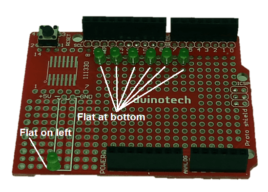
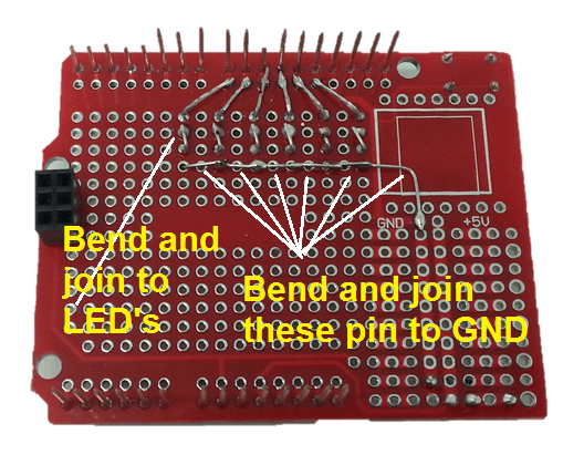
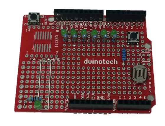
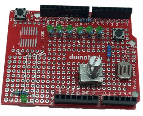
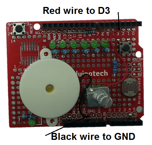
The Coding Shield gives you six LED’s, a piezo transducer, a pushbutton, an LDR and a potentiometer all wired into an Arduino Prototyping Shield. The Coding Shield can then be pushed onto an Arduino main board and used for coding without having to worry about wiring things up.
Materials Required
| 1 | Duinotech UNO r3 Main Board | XC4410 |
| 1 | Duinotech Arduino Compatible Prototyping Shield | XC4482 |
| 7 | Green 3mm LED 40mcd Round Diffused | ZD0120 |
| 1 | 4.2kHz Audio Transducer | AB3440 |
| 1 | 1.4mm SPST Micro Tactile Switch | SP0601 |
| 1 | Large Light Dependent Resistor (LDR) | RD3485 |
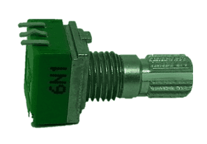
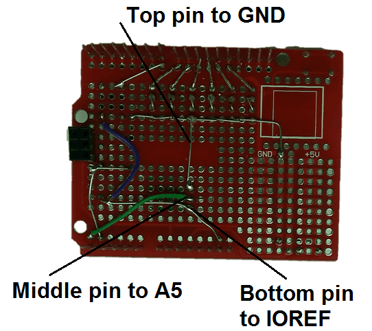
| 1 | 10k Ohm Linear (B) Single Gang 9mm Potentiometer | RP8510 |
| 1 | 470 Ohm 0.5 Watt Metal Film Resistors - Pack of 8 | RR0564 |
| 1 | 1k Ohm 0.5 Watt Metal Film Resistors - Pack of 8 | RR0572 |
| 1 | 10k Ohm 0.5 Watt Metal Film Resistors - Pack of 8 | RR0596 |
Resources
Table of Contents

Similar projects you may be interested in