Progress Bar

Skip to main content

Jaycar
...

Lithium Battery USB Charger - Powering your Arduino Project

Lithium Battery USB Charger - Powering your Arduino Project

Difficulty
TEST & TOOLS

Summary

So you’ve just finished building your Arduino project, and it’s happily running off the USB lead hanging out of your computer. And if it something like the Arduino Clock that looks at home on a desk, then everything is fine. But if it’s something you want to use away from a computer like the Secret Knock Detector, or even outside where there’s not even a power point (like the Breathalyser), then there’s a number of options. Towards the end of this article, I’ll describe a brief project to give you a flexible power supply system.

Materials Required

1Duinotech Arduino Compatible Lithium Battery USB Charger ModuleXC4502
114500 Rechargeable Li-Ion Battery 800mAh 3.7V NippleSB2300
1Duinotech Arduino Compatible 5V DC to DC Converter ModuleXC4512
115k Ohm 0.5 Watt Metal Film Resistors - Pack of 8RR0600
14AA Switched Battery EnclosurePH9282

It’s what we’ve been using so far, but we can even use the USB socket without a computer. For example, if you have a spare 

, you could use that with your USB lead. If you want to take your project outside, you could even use a 

.

These are all still fairly temporary solutions, but handy if you want to take your project away from your computer during the testing stage.

The DC socket allows a non-regulated power supply to be used on the Arduino main board, as an input here is fed through a 5V regulator before it gets to the main IC. The socket takes a 2.1mm plug with a positive centre and the regulator needs at least 7 volts to be able to work properly, but more isn’t necessarily better, as the higher the voltage, the hotter the regulator will get. Twelve volts is the recommended maximum, so if you have a 

 or 

 DC plug pack around, you could use that. It’s even feasible to use something like a 

 to run your Arduino in a car (just remember to use the 2.1mm plug end and set the plug for a positive centre).

A quick and easy portable Arduino power supply with 

An alternative to the DC Socket is the VIN pin- they are practically the same as far as input requirements are concerned, except that the VIN pin doesn’t have a reverse polarity diode like the DC socket does. All that means is that you need to make doubly sure that what you’re plugging into VIN is right, or you might fry your board. You will of course need to connect the negative leg of your supply to one of the GND pins on the board too. There’s two next two VIN and another one on the other side between D13 and AREF. Using VIN might be an easy way to feed power in through a custom shield, for example using a 

 on a 

If you have a 5V supply, you could even feed that straight into the 5V pin on the Arduino board instead of the VIN pin. The same precautions that apply to VIN apply here, as the 5V pin connects directly to main processor IC on the Arduino board. A common use for the 5V input is when you are using a module that has a built in 5V regulator, like a 

, especially because the 5V regulator on such a module might be better than the one on the Arduino board. Of course, like with VIN, you need to connect the negative of your supply to the GND pin.

And just because the pin is labelled 5V, doesn’t mean it has to be exactly 5V. Even the USB standard for 5V allows between 4.5V and 5.5V and the AtMega328 IC on the Uno can handle up to 5.5V, and is specified to work down to 3.8V when used with the 16MHz crystal on the Uno board (some people have even reported that it works fine down to 2.7V!) This could be supplied by 3xAA batteries. Why not use a 

 for your next Nano project, and the Nano can sit in one of the battery spots? If you’re using rechargeable NiMH batteries, you could use four of them, as they max out at about 1.3V each, so that you don’t go over the 5.5V limit.

Another power source close to 5V is rechargeable Lithium Ion Batteries. Although they say they are 3.7V, this is usually when they’re close to flat. An easy way to do this would be a 

 in a 

 (the 14500 is actually the same size as a AA battery). See the project below for how this is done

Generally, you can’t hook up more than one of these power supplies at a time. For example, if you find you need to reprogram the board, make sure any other power supplies are disconnected or turned off before hooking up the USB.

If you want a compact power solution, especially one that needs to fit into a case, then there are a few modules you can connect to a rechargeable battery to provide charging and even a regulated 5V output supply (this is similar to what’s in the rechargeable battery banks).

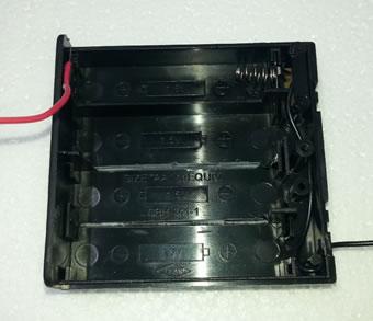
There is some soldering, cutting and gluing involved, but it shouldn’t take long to put together. Firstly, open up the battery holder and remove most of the battery springs, then move the positive battery tab to the leftmost battery slot.

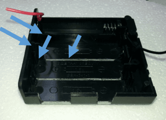
Then cut battery dividers and slots for the USB modules. If the modules are a good press-fit, then you’ll need less glue later.

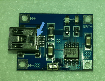
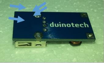
Unsolder the 1.2k resistor from the Battery Charger Module. By default, this sets the charge current to 1A, but the battery we are using is ideally charged at 80mA, so we are using a 15k resistor instead.

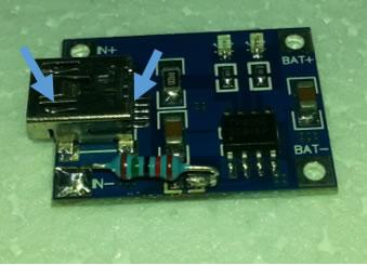
The hardest part is to replace the old resistor with the 15k resistor. Note that the resistor goes between pin 2 of the IC and ground, so we can use the larger ground pad near the USB socket.

Trim the component legs on the underside of the DC converter modules so that they are flush. Doing this will save having to trim the lid of the battery holder.

After this, solder the wires from the battery tabs to the modules. All the positive leads can be connected together, because the switch on the battery holder switches the negative lead. The negative lead from the switch should go to the DC converter module so that the output can be switched off. The negative lead from the Charge Module can be soldered directly to the battery spring (I’ve attached it to the metal tab that leads to the switch). You shouldn’t need any extra wire if you use the spare leads from the battery holder.

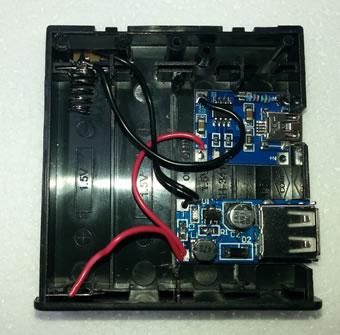
Note how I’ve pushed the DC converter module to the right slightly so that it’s poking out of the case. That leaves a bit more room inside the battery holder for either a second battery or even a Nano!

Make sure the lid fits on, then glue the modules down. I used 

, but 

 would work as well. After the glue is set, insert the battery. If you turn the switch on, the light on the DC Converter should light. If you plug a USB lead into the Charge Module should light up red (or blue if the battery is fully charged). You can charge and use the output at the same time because the two modules are completely independent. Keep in mind that we’re only charging at 80mA, and that the DC Converter module can only output 500mA, so it’s not going to be much good for charging a mobile phone. If you are using more than 80mA out of the DC Converter, even while charging, the battery will be discharging.

As I mentioned above, most Arduino boards will happily run straight off a Lithium battery, so you could even ditch the DC converter module and run the power from the switch straight to the Arduino board- a Nano will fit in the battery holder if its ISP pins are removed (these are the ones that poke up on the top of the board. It’ll be even smaller if the header pins are all removed.

There’s also just enough room to fit a second battery- here’s where you can use the spare battery springs that you removed earlier. Just remember to connect all the batteries is parallel- ie positive to positive and negative to negative. You’ll have less space available, but longer running times.

Similar projects you may be interested in

Installing and Setting Up the XC0440 Weather Station
TEST & TOOLS
Installing and Setting Up The XC0440 Weather Station
Difficulty

TEST & TOOLS
Personal Weather Station
Difficulty

TEST & TOOLS
Coding Shield Project
Difficulty

TEST & TOOLS
How to remove Header pins
Difficulty