Progress Bar

Skip to main content

Jaycar
...

Digital Photo Frame

Digital Photo Frame

Difficulty
Sight & Sound

Summary

Use our new WiFi UNO and 240 x 320 TFT screen!

Share your memories or get the latest in memes automatically with this Wi-Fi enabled Photo Frame. Using our newest UNO with Wi-Fi board and a 320x240 touch screen display, simply provide a list of JPEG links and the photo frame will rotate through and display them automatically.

Can be used with the popular service IMGUR to get daily content automatically.

Materials Required

1Duinotech UNO r3 Main Board with Wi-FiXC4411
1Duinotech Arduino Compatible 2.5 Inch Colour LCD Touch Screen DisplayXC4630

Table of Contents

Radio on Protoshield

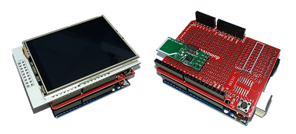
This is similar for both units so it is a good place to start. Get two radios and two shields and solder them similar to the following pictures:

The radio hangs over the bottom of the shield to allow for better radio reception.

Test Radio Connections

Mount the shield on both of the UNOs and mount the LCD on one as the receiver. The transmitter has not been connected to any sensors yet but that is ok as we're just testing the radio link.

Download the sketches that go along with this project and upload onto each UNO. You should be able to check that the LCD screen initialises and displays something like the following:

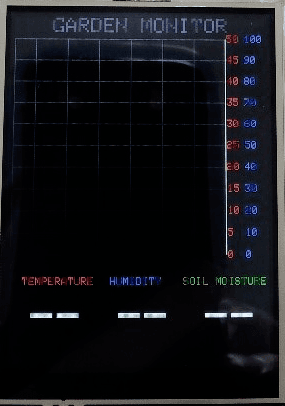
If the radios are both working correctly you'll see a green 'R' flash in the top right corner of the display about every five seconds and after a few minutes numbers and graph lines will appear.

If the radios are not working check the wiring for both prototyping shields.

Sensors on Transmitter

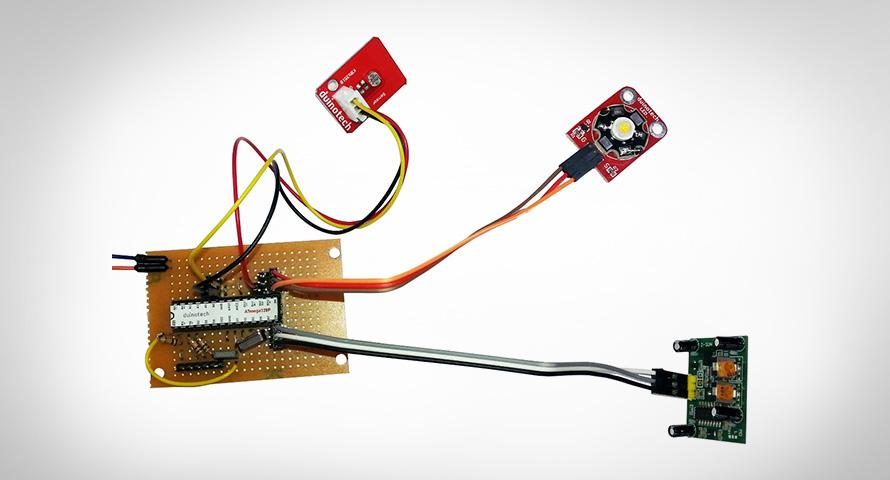
The receiver unit is complete, but the transmitter (the one without the screen) should be powered down so we can add the sensor modules. We've used two groups of red, brown and orange wires from the WC6028 and wired the reds to the +5V bus and the browns to the GND bus at the end of the Prototype Shield.

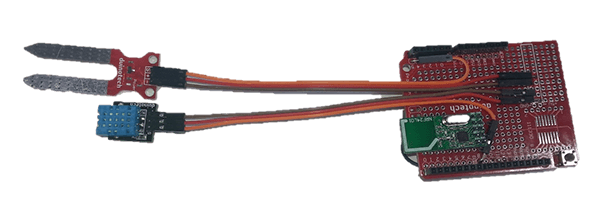
See how the pin ends are staggered to keep the cables flat. The orange for the Soil Sensor goes to A5 and the orange for the Temperature and Humidity Sensor goes to D8. The modules can then be plugged in at the other end.

The transmitter unit can now be powered up again and after a minute we should see valid data appearing on the display.

Install

The final step will be to install the units where they can be used. You might need to fit a rainproof container if the transmitter is to be set up outside and also extend the Soil Sensor wires.

Download the source code and extract into a new folder, open the .ino file in the Arduino IDE and press upload.

There is not much to operating the transmitter as it automatically transmits about once every five seconds. The code for the transmitter simply initialises everything, reads the sensors, then transmits the data along with a checksum code and waits five seconds until the next transmission is needed.

The receiver is a bit more complicated and most of the code is to do with drawing and updating the screen. During the setup() function the screen and radio module are initialised and some of the unchanging parts of the screen are drawn (title, y-axis and text at the bottom of the screen). During the loop() function the UNO mostly waits for radio data, then every minute (this can be changed by the SAMPLET value) the most recent data is saved to an array. If it's a multiple of 15 minutes this is also saved to another part of the array and similarly if it's a multiple of two hours. This gives us samples that cover either an hour, a day or a week. After a sample is saved the rest of the screen is redrawn: the graphs, x-axis and large numbers at the bottom of the screen.

In loop() the sketch also checks the touch panel and if a touch is detected at the bottom of the screen the x-axis is changed and the screen is redrawn with the appropriate data for an hour, day or week display. If the graph area of the screen is touched the cursor is moved to highlight a different part of the graph. Note that the large numbers at the bottom of the screen correspond to the value under the cursor and not the current values.

Similar projects you may be interested in

Atari Punk Synth
Sight & Sound
Atari Punk Synth
Difficulty

Silent Alarm Clock
Sight & Sound
Silent Alarm Clock
Difficulty

Sight & Sound
Ultrasonic Parking Assistant
Difficulty

Sight & Sound
Arduino Power Saving and Battery Night Light
Difficulty