WiFi Controlled Strip Lighting
Summary
Control some dazzling RGB effects with ESP8266 and Vue.js Web App! Want to decorate your loungeroom or living areas with cool lighting effects from your mobile phone? With this kit you can!
Materials Required
| 1 | RGB LED Flexible Strip Light Water Proof | SL3954 |
| 1 | Wi-Fi Mini ESP8266 Main Board | XC3802 |
| 1 | 2N7000 N-Channel FET | ZT2400 |
| 1 | 1k Ohm 1 Watt Carbon Film Resistors - Pack of 2 | RR2774 |
| 1 | 7805 +5V 1A Voltage Regulator TO-220 case | ZV1505 |
| 1 | 10uF 25VDC Electrolytic RB Capacitor | RE6070 |
| 1 | 1uF 25VDC Tantalum Capacitor | RZ6627 |
| 1 | Ultra Mini Experimenters Board | HP9556 |
| 1 | 2 Way PCB Mount Screw Terminals 5mm Pitch | HM3172 |
| 1 | 3 Way PCB Mount Screw Terminal - 5mm Pitch | HM3173 |
Table of Contents
.png%3Fbranch%3Dprod&w=3840&q=75)
More or less a simple system conceptually; the esp provides a
website
that shows up like a makeshift Web-App on your phone. When you use the app to set the speed and colour of the strip lighting, the ESP will then process the parameters and activate the effects.
So far the effects we have done (as of 20/09/2019) are:
More?
What effects do you want to see?
Check the github repository for the latest:
For this example we have 2 effects done; but we want more. Pull requests and code improvements through Github are well recommended and is a great way to learn. Contribute what you want, the worst we can do is correct it and send it back.
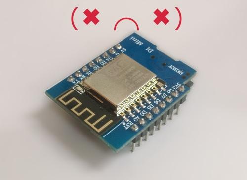
The main work of this project involves the ESP8266 controller board
The
main board is used and has its own manual on how to enable it in the Arduino IDE; be sure to read and apply that first before trying to program the ESP; you can go do that now and come back to this project at any time :smiley:.
We are using pin D7 to control the Strip lighting; A quick point of reference (for the programming segment later): D7 is not accessed through the literal number 7 but instead by the designator D7.
Thus:
1pinMode(D7, OUTPUT);digitalWrite(D7, HIGH);digitalRead(D7);2
The literal D7 is only defined via the LOLIN(WEMOS) D1 R2 & Mini board setting, in the Tools->Board menu of the Arduino IDE.
In addition to this; we are storing our website on the ESP in flash memory, so we must use <SPIFFS.h> library which is included in the board management from above.
You should make sure you remember to set the flash size in the board settings, for this project we use
4M (3M SPIFFS)
size.
The circuit is a simple one; as we are using 12v source (as needed by the lights) we pass that through to the light circuit, and use a small
to control the DIN line to the striplight.
The general schematic is like this; note the orange wire.
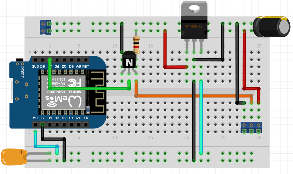
Above:
breadboard version
.png%3Fbranch%3Dprod&w=1920&q=75)
It might start to look complicated but this is quite a simple circuit to pay attention to:
12V comes in via the connector on the left, with the top rail being +12v and the other being ground.
12V flows across the board to the other connector
GND follows around the underside of the board, and connects to the connector.
The middle SIGNAL-OUT connects to the top pin of the FET; and has the resistor between it and 12V.
the middle pin of the FET connects to D7 on the ESP8266.
There is a 7805 circuit that powers the ESP8266; this is a simple VIN, VOUT circuit, with capacitors on each of side.
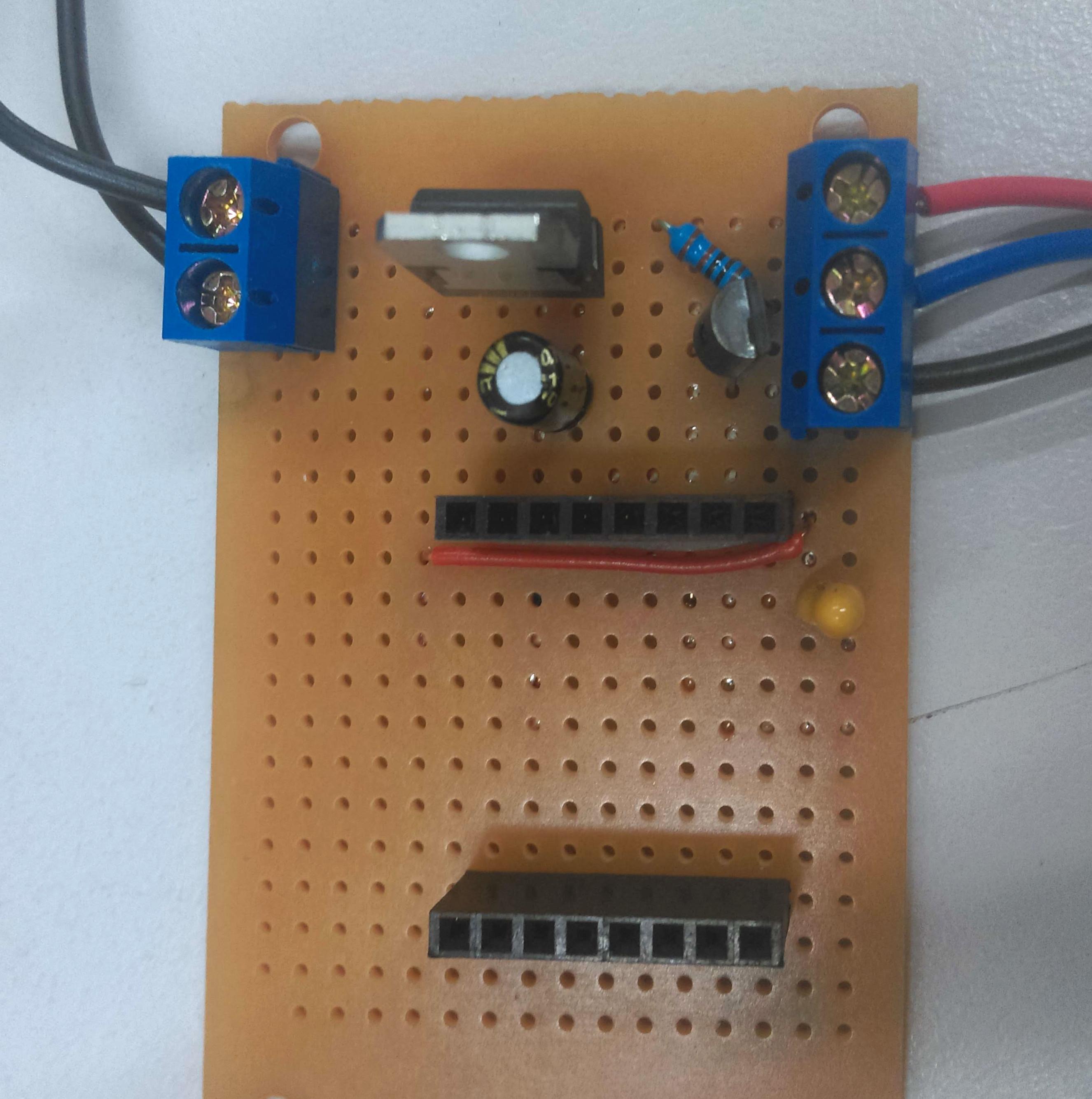
Depending on the PCB / veroboard that you've chosen to use for this project will determine how it's laid out; however if you're going with this tutorial and you're using the PCB board that we've supplied, you might find something a little bit like this:
Given the connections on the underside of the board, there's a bit of work to get it so that it is not shorting itself out. Below is some photos of our board to help you, but try to follow along to make sure that things are connected as they should be. Haste makes waste.
The last photo of this segment is flipped so that you can see how it corresponds to whats under the board; make sure you do not copy this image, it is just for reference so you can visualise where each connection is going.
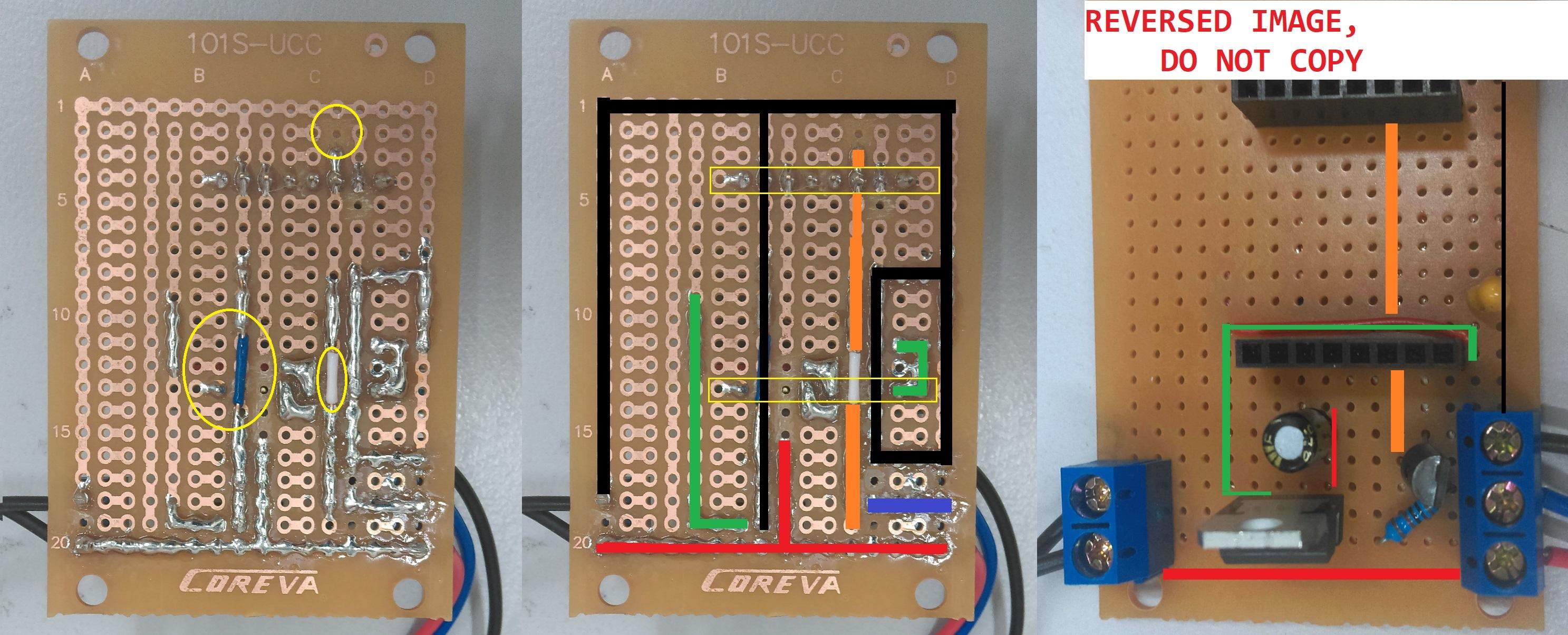
Follow the advice below so you can visualise it better; Note that there are bridges on both the
ORANGE
and
BLACK
lines, so that they are not connected the pins underside. This is important and are highlighted in the yellow circles on the first image.
Colour | Circuit |
|---|---|
Black | Ground connection |
Red | 12V connection, connected to capacitor |
Green | 5V connection, coming out of 7805 chip |
Purple | Signal connection, resistor to 12v, coming from top pin of FET |
Orange | ESP signal connection, connected to D7 and middle pin of FET, Bridged over D4 connection |
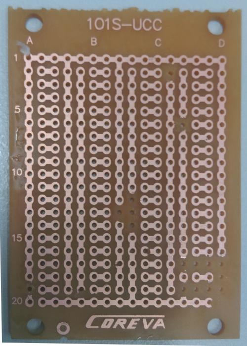
Below is a blank PCB that has had the correct traces cut; if you're still stuck you can copy this below by using a small knife to remove the traces, then simply place the above components and try to copy the above. If you are going your own way in regards to the PCB, just ensure to follow the images at the start of this section.
And finally,
please do not connect 12v to your ESP, on any pin.
Test and make sure with a multimeter that the 5V pin is 5V, and the other pins are not shorted.
The "
Web App
"/Website portion of the software is located in the data folder and is written in HTML/Javascript; It mainly uses the
library to make a visually pleasing interface.
Connecting the ESP to the network is a pretty easy process and we have simplified the parameter settings for you. We like this method and will continue it in future projects.
The parameters for connecting to your network is as follows:
1void setup(){ //... setupNetwork("yourWifiName", "yourWiFiPassword"); setupMDNS("NameOfYourDevice"); //..}2
void setup(){ //... setupNetwork("yourWifiName", "yourWiFiPassword"); setupMDNS("NameOfYourDevice"); //..}
You can change NameOfYourDevice to any singular lower-case word, for instance: loungeroom, coollights, prezzie; you will then be able to access the device through:
http://nameofyourdevice.local/
If you have multiple devices, they must all have unique names.
You can simply use the
and upload the data folder to the ESP; We won't explore too much into the web-programming side of it; but some points of reference:
Bootstrap vue creates custom elements such as <b-btn> - read more about
components
on the bootstrap vue website.
we use jscolor.js from
as a library to produce our colour picker; this has been
in our data folder.
controller.js is the main javascript control application and is written in
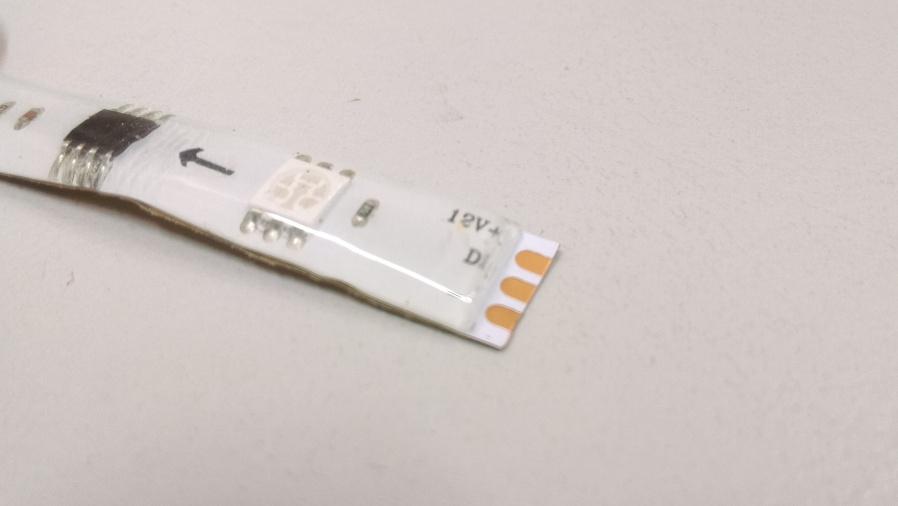
The strip light is an easy 3 wire connection; You'll find them labeled as
VCC - connected to 12V
DIN - connected to DATA port
GND - connected to ground
Simply snip off along the cut line, then use a stanley knife to trim away some of the waterproof coating.
Once the copper pads are exposed; use a soldering iron to apply a blob of solder to the pad; you can then tin some wires and place them into the solder blob, so you have a nice solid connection. Be sure to colour code your wires so you know which one is which, this can be easily done with the
that we sell.
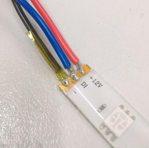
It will generally be a good idea to protect the joints with heatshrink if you have any available.
Connect the strip-light into the 12V/DOUT/GND port of the circuit board, then connect power into the 12V/GND port of the circuit-board.
Test your connections, if you apply 12v to the ESP you will burn the chip out. As long as you're reading 5v on the 5v pin then you're fine: plug in the board, with the correct orientation.
Check your network, you should see the Striplighting hotspot show up and you can connect to it on your phone; OR if the device connected to your network, you can try http://striplight.local - depending on how you have it set up as mentioned in the "
" section.
Once things have been set up, simply open up up the website of the ESP and you should be greeted with a website that looks similar to below:
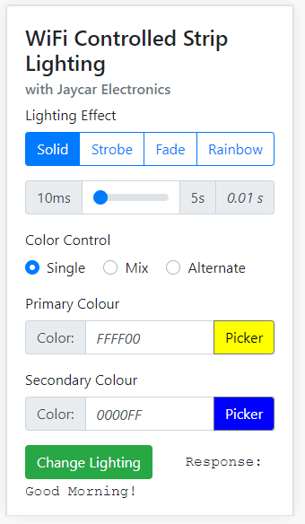
Here you will be able to change different effects, the rate of change, and most importantly, the colour and brightness.
(note: The rainbow effect will have no effect)
This error is simply that the website has not been uploaded to the flash data; make sure that you set the correct flash size in the tools menu to flash size : 4M (3M) SPIFFS and use the
to upload data to the SPIFFS of the ESP.
If you have changed the flash size in the tools menu, it would be best to re-upload the sketch so that the data is laid out correctly.
Future Improvements
Definitely more effects, more options, more everything; this project has a huge avenue for improvement:
Similar projects you may be interested in