Duinotech Uno Programmer
Summary
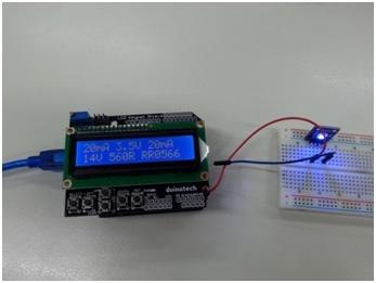
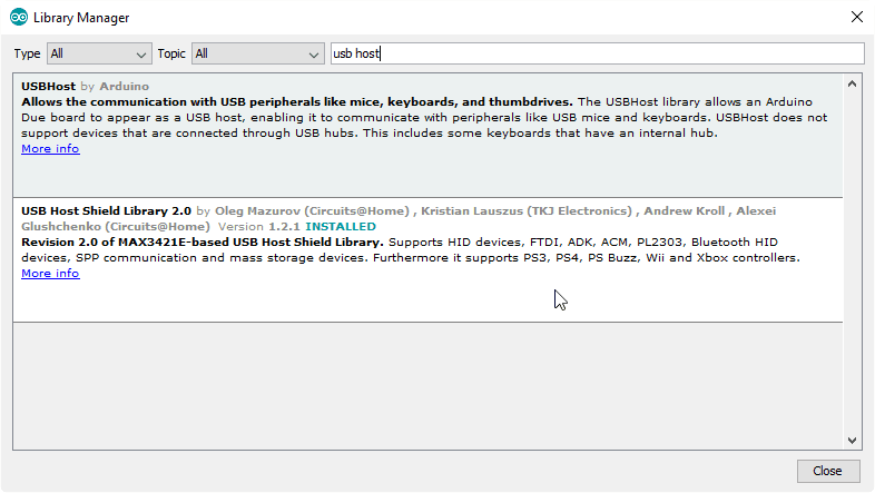
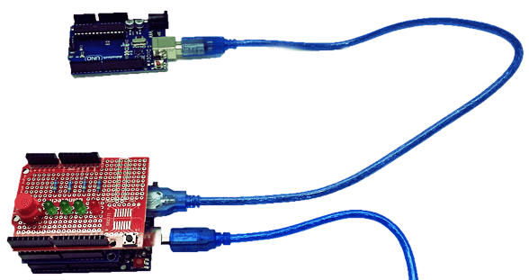
Recently, we had to program a big pile of Uno's for some workshops we were running, getting kids to build the Snake Game Project. We didn't want to worry the kids with the programming side of it, so we needed a pile of preprogrammed Uno's for them to build with. The idea of using an Uno to program an Uno sounds a bit meta, but with a USB Host Shield, we managed to program our Uno's. In fact, the programming only takes about three seconds per board, which is even faster than we could unpack them. Some soldering required.
Materials Required
| 1 | Duinotech UNO r3 Main Board | XC4410 |
| 1 | Arduino Compatible USB Host Expansion Board | XC4456 |
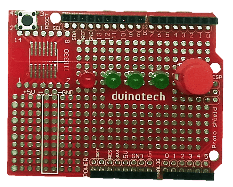
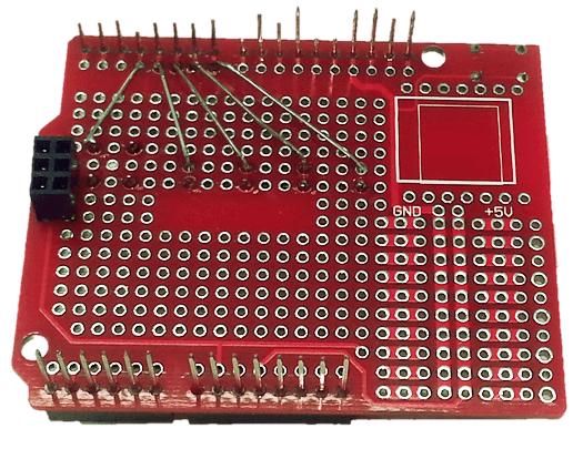
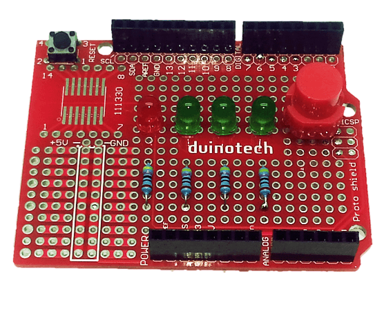
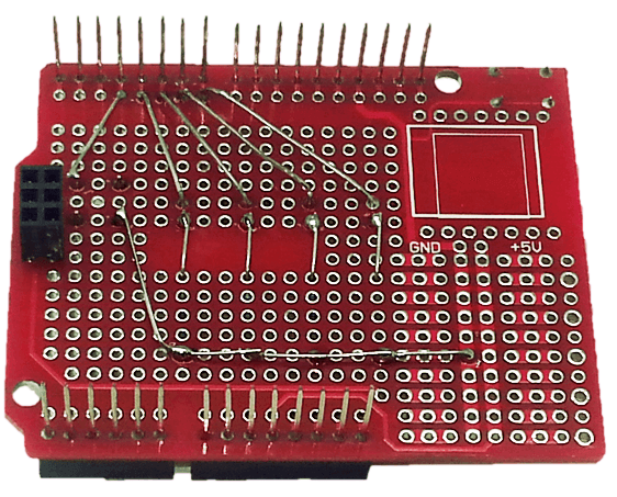
| 1 | Duinotech Arduino Compatible Prototyping Shield | XC4482 |
| 1 | Red 5mm LED 8mcd Round Diffused | ZD0150 |
| 3 | Green 5mm LED 80mcd Round Diffused | ZD0170 |
| 1 | 470 Ohm 0.5 Watt Metal Film Resistors - Pack of 8 | RR0564 |
| 1 | Red Snap Action Keyboard Switch - PCB Mount | SP0720 |
Resources
Table of Contents
.png%3Fbranch%3Dprod&w=1080&q=75)

.png%3Fbranch%3Dprod&w=3840&q=75)
Future Improvements
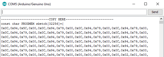
Although this function may be of limited use, it is possible to program the Duinotech Uno Programmer sketch to the target. In the sketch file, there are the lines:
Similar projects you may be interested in