Progress Bar

Skip to main content

Jaycar
...

Trailer Voltage Monitor

Trailer Voltage Monitor

Difficulty
Test & Tools

Summary

One of the guys at the office here asked if I could build an Arduino device for monitoring the voltage of the 12V battery in his trailer- as now required for registration of some trailers which have electric brakes. Here’s what we built- and it’s a bit cheaper than some of the offerings out there.

Materials Required

1Duinotech Leonardo r3 Main BoardXC4430
1Arduino Compatible RGB LED ModuleXC4428
110k Ohm 0.5 Watt Metal Film Resistors - Pack of 8RR0596
14.7k Ohm 0.5 Watt Metal Film Resistors - Pack of 8RR0588
128 Pin Header Terminal StripHM3211

As you can see, the construction is quite straightforward. Snap off a length of four header pins, and insert them into the headers on the Arduino to hold them steady (it doesn’t matter where for now). Solder the resistors like this:

You might find it easier to trim one leg of the resistor while you hold the other leg, then trim and bend the other leg before soldering. Note that the 4.7kOhm resistor goes between the two outside legs, and that the 10kOhm resistor goes between the first and third legs.

Insert the above ‘module’ into the Leonardo so that the 4.7kOhm resistor is above GND, the 10kOhm resistor is above VIN and the shared resistor leg goes into A0:

Then plug the RGB LED Module into D4-D7 as below:

See how we’ve gently bent the resistors and LED Module so they sit a bit flatter. This is the end of our construction.

This sketch is quite straightforward and doesn’t need any external libraries. It’s a bit long because we’ve set a few defines to make it customizable if we need to. Select your board and serial port from the Arduino IDE and press upload. The light should come on red (because it’s being fed from less than 11.5 Volts). If nothing happens, check that the LED wiring is right. If you get a green light, your resistor wiring might be wrong.

The simplest way to connect the Trailer Voltage Monitor is to run some wires from the battery you are monitoring to a 

, and plug that into the DC jack on the Leonardo. This will cause the LED to light up green if the voltage is above 11.5V, and red if the voltage is below 11.5V. Below about 7V, the LED will not light up at all, and this is what will happen if you have a breakaway.

If you want a better indication that there is a breakaway, you can also feed 5V to the Leonardo through its Micro USB socket. That way, if no power feeds in from the monitored battery, power is supplied from the Micro USB Socket. That’s also why we chose the Leonardo- it’s easier to find a car charger with Micro USB than the USB-B on the Uno.

The onboard voltage regulator of the Leonardo has a maximum input voltage of 20V, so unfortunately, cannot be used directly with a 24V system. If you wanted to rig up an external regulator to bring the 24V down below 20V, and also change out the 10kOhm resistor for something 30kOhm or higher, then this is possible- note you’ll also need to change the RVIN definition below.

If you do want to change any of the other configuration parameters, such as resistor value or voltage threshold, this can be done in the #defines in the code.

Another enhancement you could make is to add a 

 to give audible warning of the voltage. If you had a buzzer wired up with GND going to - on the buzzer and D12 going to S on the buzzer (which can be done by simply pushing it into the Leonardo headers), you could put:

tone(12, 400, 100); //sound tone

in the line after

ledset(1,0,0);//red

So that any time the red LED is on, the tone is triggered.

1 //Trailer Voltage Monitor
2 //For power brakes etc.
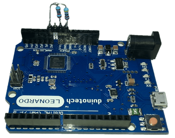
3 //supply Arduino through VIN/GND or DC jack from Trailer battery
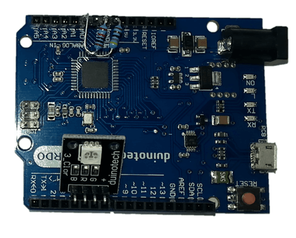
4 //LED is green if OK, red if low and off!! if disconnected
5
6 //define led module pins here, polarity is automatically handled by presence of LEDPLUS or LEDMINUS
7 //if LED's have common negative, use LEDMINUS
8 //if LED's have common positive, use LEDPLUS
9 //#define LEDMINUS 3
10 #define LEDPLUS 7
11 #define LEDBLUE 4
12 #define LEDRED 5
13 #define LEDGREEN 6
14
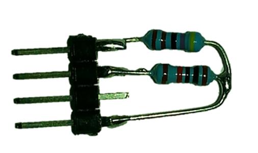
15 //Set resistors here:
16 #define RVIN (10000.0)
17 #define RGND (4700.0)
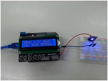
18 #define VTRIGGER (11.5)
19
20 void setup() {
21 ledsetup(); //set up pins
22 }
23
24 void loop() {
25 int a=analogRead(A0); //read input
26 float v;
27 v=(a*5*(RVIN+RGND))/RGND/1023; //work out v at VIN based on resistors
28 if(v ledset(1,0,0);//red
29 }else{
30 ledset(0,1,0);//green
31 }
32 delay(200);
33 }
34
35 void ledsetup(){ //set up led pins depending on whether they are common + or common -, turn all LED's off
36 #ifdef LEDPLUS
37 pinMode(LEDPLUS, OUTPUT);
38 digitalWrite(LEDPLUS, HIGH);
39 pinMode(LEDRED, OUTPUT);
40 digitalWrite(LEDRED, HIGH);
41 pinMode(LEDGREEN, OUTPUT);
42 digitalWrite(LEDGREEN, HIGH);
43 pinMode(LEDBLUE, OUTPUT);
44 digitalWrite(LEDBLUE, HIGH);
45 #endif
46 #ifdef LEDMINUS
47 pinMode(LEDMINUS, OUTPUT);
48 digitalWrite(LEDMINUS, LOW);
49 pinMode(LEDRED, OUTPUT);
50 digitalWrite(LEDRED, LOW);
51 pinMode(LEDGREEN, OUTPUT);
52 digitalWrite(LEDGREEN, LOW);
53 pinMode(LEDBLUE, OUTPUT);
54 digitalWrite(LEDBLUE, LOW);
55 #endif
56 }
57
58 void ledset(byte r, byte g, byte b){
59 #ifdef LEDPLUS
60 r=!r; //invert if we're using common +
61 g=!g;
62 b=!b;
63 #endif
64 digitalWrite(LEDRED, r); //set outputs
65 digitalWrite(LEDGREEN, g);
66 digitalWrite(LEDBLUE, b);
67 }

Future Improvements

Similar projects you may be interested in

Portable Soil Moisture Meter
Test & Tools
Portable Soil moisture meter
Difficulty

Test & Tools
Wireless Garden Monitor
Difficulty

Arduino Based LED Tester
Test & Tools
Arduino Based LED Tester
Difficulty

Test & Tools
IoT Smart Wireless Switch
Difficulty