Progress Bar

Skip to main content

Jaycar
...

Tiny85 Game

Tiny85 Game

Difficulty
Entertainment
test image

Summary

We're glad we've got the ATTiny85 IC because now we can build some really tiny projects. Inspired by Dombeef's pockeTETRIS game we set about building our own version and even creating a new game that runs on the same hardware. Our version isn't as tiny as some we've seen - like the one at http://webboggles.com/attiny85-game-kit-assembly-instructions/ but we haven't got around to designing a custom PCB yet.

Materials Required

1ATTiny85 IC 8 pin DIP8ZZ8721
1Ultra Mini Experimenters BoardHP9556
1Arduino Compatible Monochrome OLED Display ModuleXC4384
140 Pin Female Header StripHM3230
31.4mm SPST Micro Tactile SwitchSP0601
18 Pin Production (Low Cost) IC SocketPI6500
110k Ohm 0.5 Watt Metal Film Resistors - Pack of 8RR0596
120mm Button Cell Battery HolderPH9238
1Panasonic CR2032 Lithium BatterySB2944

ATTiny pin

Connections

1

Resistor to + (pin 8)

2

OLED SDA

3

OLED SCL

4

Battery - and OLED GND

5

Right Button

6

Left Button

7

Middle Button

8

OLED VCC and Battery +

The Experimenter's Protoboard comes as two similar halves so snap it in half. The important things to orient ourselves are the copper tracks and the row and column number, so don't worry about the alignment of the other writing too much.

Note, there is one copper trace that goes around the side of the board. Place the Tactile Button Switches on the board as shown above and solder in place. The trace labelled in orange above (that goes around three sides of the board) will be connected to the positive battery terminal and the trace labelled in black will go to the negative battery terminal.

The next step is to solder the IC socket in place. If you would like to make a slimmer version of the game you can eliminate the IC socket and header socket for the display, but this will make it much harder to debug and reprogram the game. The notch in the IC socket faces furthest away from the buttons so that pin 1 is in row 9.

Note how we've deliberately bridged pins 4 and 8 (remember we are looking at this from the back) to the busses running up the middle of the board - these will be our main power connections and this method makes wiring a lot easier.

To mount the OLED display cut the HM3230 female header strip at the fifth position so that you get a length of four pieces. This is soldered to the prototyping board using rows 8-11. The pin in row 10 is bridged to the right and the pin in row 11 is bridged to the left.

Then set up four resistors as shown: (NB: Excuse the red, not sure where these were originally pointing towards.)

Take the top leg of the right hand resistor and attach it to pin 5 of the IC socket - this will be the first pin directly in line.

The rest of the legs can be trimmed but keep the offcuts to make some short links between the two top pins of the header socket and pins 2 and 3 of the IC socket.

Mount the battery holder as shown making sure the connections go to the positive and negative rails.

The last bit of soldering is to run some short pieces of wire from pins 6 and 7 on the IC socket to the other two pushbuttons (the easiest point to solder to is the exposed leg of the resistor).

You can test fit the ATTiny85 IC and OLED display to make sure it all looks OK - be careful with the pins of the IC as they will bend very easily, especially when trying to remove the IC from the socket. A good trick is to install the IC into a second socket to protect the pins from repeated removal while you are programming and testing.

Do not insert the battery yet - we need to program the ATTiny85 IC and if this is done in place the programmer will put 5V on the battery which might damage it.

If you have built the ATTiny Programmer shield you can use that. An ISP programmer like 

 will also work, although it might need to be set to slow mode. If you have either of these you can jump straight to the Sketch uploading section.

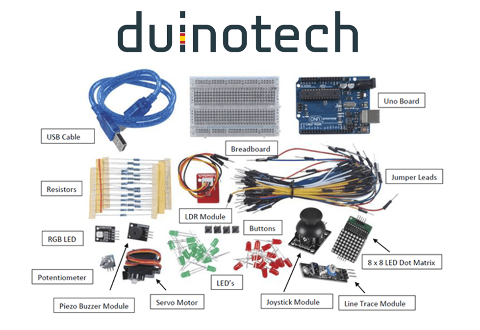
Otherwise, you can make a very simple ISP (In System Programmer) using an Arduino Board (an UNO is preferred but other boards might work with different wiring configurations), some plug-plug jumpers, a 10 uF or greater capacitor and a spare 

 8 pin socket. Program the UNO with the ArduinoISP sketch from File>Examples>11.ArduinoISP>ArduinoISP then unplug it from the computer. Take a group of 6 jumper leads (we used brown/red/orange/yellow/green/blue) and plug them from the UNO to the IC socket as follows - the plugs fit into the socket just like an IC leg would. Also fit the capacitor between RST and GND.

UNO

IC Socket

5V

Pin 8

GND

Pin 4

D10

Pin 1

D11

Pin 5

D12

Pin 6

D13

Pin 7

To attach the programmer to the ATTiny85 gently push it down on top of the IC so that the corresponding pins are connected and hold it there while programming is occurring.

By default the Arduino IDE does not support the ATTiny85 IC. If you do not have this support installed it can be added by following the instructions here: 

.

If you are using a brand new ATTiny85 it will probably need to have a bootloader installed. In this case, there isn't any actual bootloader code as such but there are some 'fuse' settings which set certain things like processor speed and clock source. For a new IC use the Tools menu to select 'Board' as ATTiny25/45/85, 'Processor' as ATTiny85 IC and 'Clock' as 8MHz internal clock.

Be very careful with the clock setting as you may find it difficult to reprogram the IC if an external clock source is selected.

Connect the programmer, make sure the correct programmer type is selected from the menu and then click 'Burn Bootloader'. The programmer should flash for a few seconds and you should see a message that the Bootloader Burn was successful. At this point, you should be able to install Dombeef's pockeTETRIS game.

For pockeTETRIS, go to the GitHub page at 

 and download the .zip file. Extract the pockeTETRIS_arduino folder and copy it to your sketch folder then open the pockeTETRIS_arduino.ino file with the IDE.

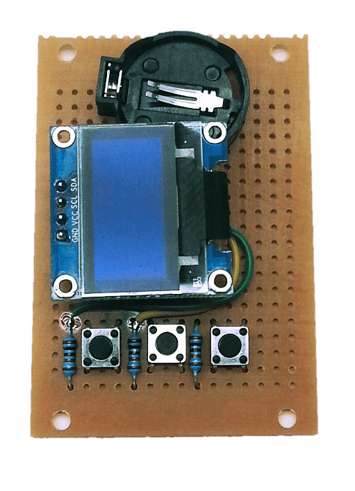
The code doesn't need any changes to work with our hardware so you should simply be able to click 'Upload' to compile and upload the sketch. Make sure the IC is in place, then attach the OLED and finally insert a button battery. The splash screen should appear and the game starts a few seconds later.

If you find the game is very slow you might not have correctly burned the bootloader - so the game thinks everything is running at 8 MHz but the processor is actually running at 1 MHz.

Hopefully, the game is self-explanatory - the left and right buttons move the pieces left and right and the centre button rotates the piece. You don't need to remove the battery when you aren't playing - the sketch includes code that puts everything into a low power mode after the game ends. It can be woken up by pushing any button.

Future Improvements

Similar projects you may be interested in

Entertainment
Arduino Learning
Difficulty

Entertainment
Music Beat Bar
Difficulty

Metronome
Entertainment
Metronome
Difficulty

Entertainment
Memory Gesture Game
Difficulty