Programmable Remote Control
Summary
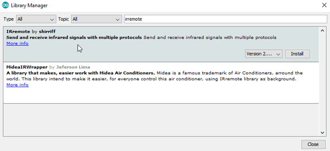
One of the really great things about the Arduino community is how many extra features they have added to the IDE. In this project, we'll be using a library which has been created by one of the members of the Arduino community, and has been added to by other members. It's a Programmable Remote Control, which is perhaps similar to a 'Learning Remote Control', except that it can give a lot more information about the codes it is sending. Check out the library documentation for the protocols that are supported. Some soldering required!
Materials Required
| 1 | Duinotech UNO r3 Main Board | XC4410 |
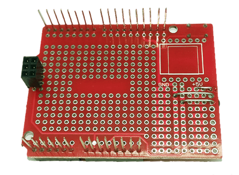
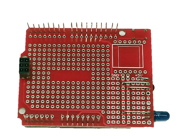
| 1 | Duinotech Arduino Compatible Prototyping Shield | XC4482 |
| 1 | 28 Pin Header Terminal Strip | HM3211 |
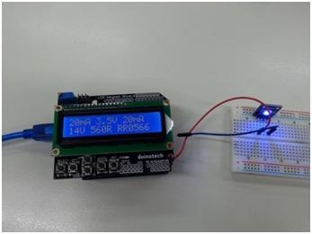
| 1 | 470 Ohm 0.5 Watt Metal Film Resistors - Pack of 8 | RR0564 |
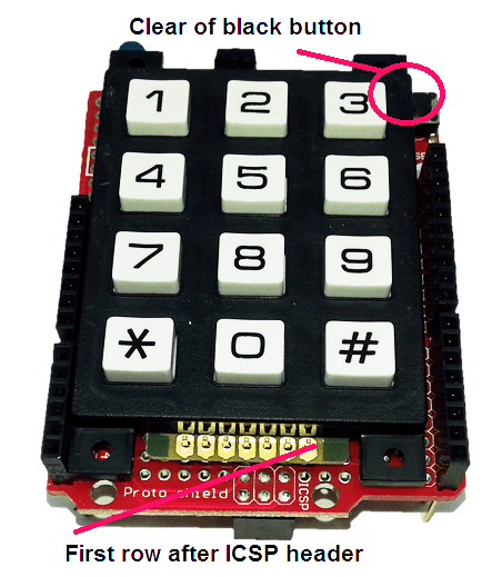
| 1 | 12 Key Numeric Keypad | SP0770 |
| 1 | IR LED Receiver | ZD1953 |
| 1 | 5mm Infrared Transmitting LED | ZD1945 |
| 1 | Yellow 5mm LED 70mcd Round Diffused | ZD0160 |
Table of Contents
Future Improvements
The hardware is a handy combination, and can be used in a few different ways, because it has a receiver and transmitter. You could have a completely different sketch that can receive one signal, and then activate some other signals- for example, to turn on the amplifier at the same time as the stereo.
Similar projects you may be interested in