Progress Bar

Skip to main content

Jaycar
...

Power and Arduino

Power and Arduino

Difficulty
Power

Summary

There's a heap of modules and shields for controlling power with Arduino, for example the XC4488 MOS Driver, XC4472 Motor Driver Shield or even the XC4418, XC4419 or XC4440 relay modules.

But if you want to explore things at more of a component level, or the existing products are too big or doesn't quite do what you need, then it can help to know how to use transistors and H-bridge drivers. The most common reason for using any of these parts is to be able to control a higher voltage or current than an Arduino would normally allow. An Uno's pins can't go any higher than 5.5V and can't supply more than 40mA (and that's absolute maximum). If you want to drive something like a motor, solenoid, relay or even a speaker, then you'll need extra components. You could lay them out on a breadboard for prototyping, and then build a custom shield if you need a more finished solution.

Materials Required

1Duinotech UNO r3 Main BoardXC4410
1Arduino Compatible Breadboard with 830 Tie Points PB8815
1150mm Plug to Plug Jumper Leads - 40 PieceWC6024
1DC Geared Motor with Rubber WheelYG2900
1MOSFET IRF1405 N-Channel 55V 169A TO-220ZT2468
1PN100 NPN Multi-replacement TransistorZT2283
11k Ohm 0.5 Watt Metal Film Resistors - Pack of 8RR0572
110k Ohm 0.5 Watt Metal Film Resistors - Pack of 8RR0596
11N4004 1A 400V Diode - Pack of 4ZR1004
1L293D Dual Full Bridge Motor Driver ICZK8880

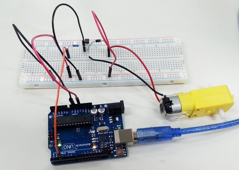
If you have something that simply needs to be on or off, then a transistor will probably do the job. If we look at the MOS Driver module, we can see there are not many components to it:

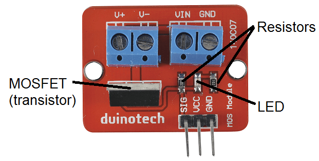
One of the resistors and the LED are simply used to indicate that the 'signal' pin is on. The minimum needed is the MOSFET and a resistor (the resistor ensures that the MOSFET is turned off if there is nothing connected to the SIG pin). This version, using an N-Channel MOSFET (actually a 

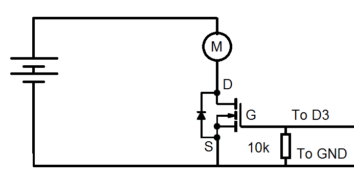
), is what is called a 'low-side switch', as it switches the load on the side closest to ground, like this:

Although this means that the motor is normally floating and connected to the higher voltage, it also means that a low voltage device like the Arduino can control a higher voltage device. If it was a high-side switch, then the Arduino would have to connect to the higher voltage, which would be harder. Note in the circuit below the pins of a MOSFET are referred to as Gate, Drain and Source. Check the datasheet if using a different MOSFET, as they might be in a different order, and some might have different ratings. This MOSFET is rated up to 55V and 169A, and may need up to 4V on the Gate to activate the MOSFET. For example, the 

 MOSFET is smaller, has a different pin order and can only drive up to 200mA but this would probably be sufficient for switching relay coils. A P-Channel MOSFET could be used as a high-side switch, but this requires a different circuit. I’ll examine other options for high-side switches later in this article.

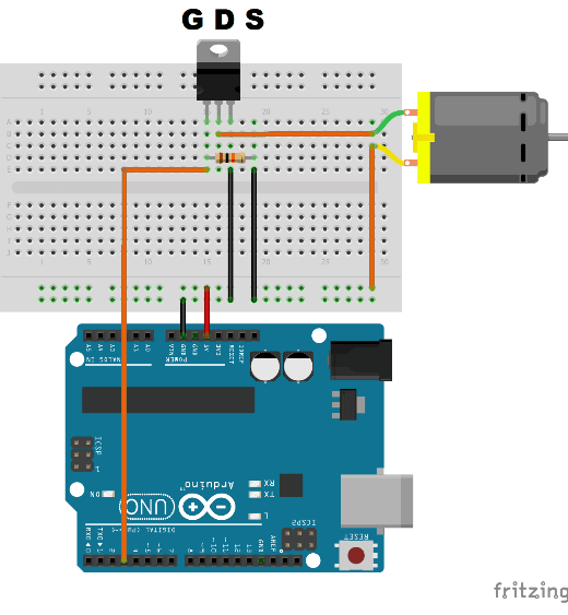
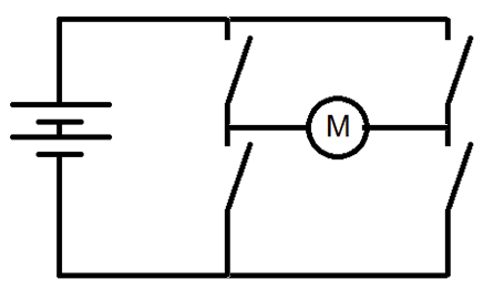
Here is the equivalent circuit diagram:

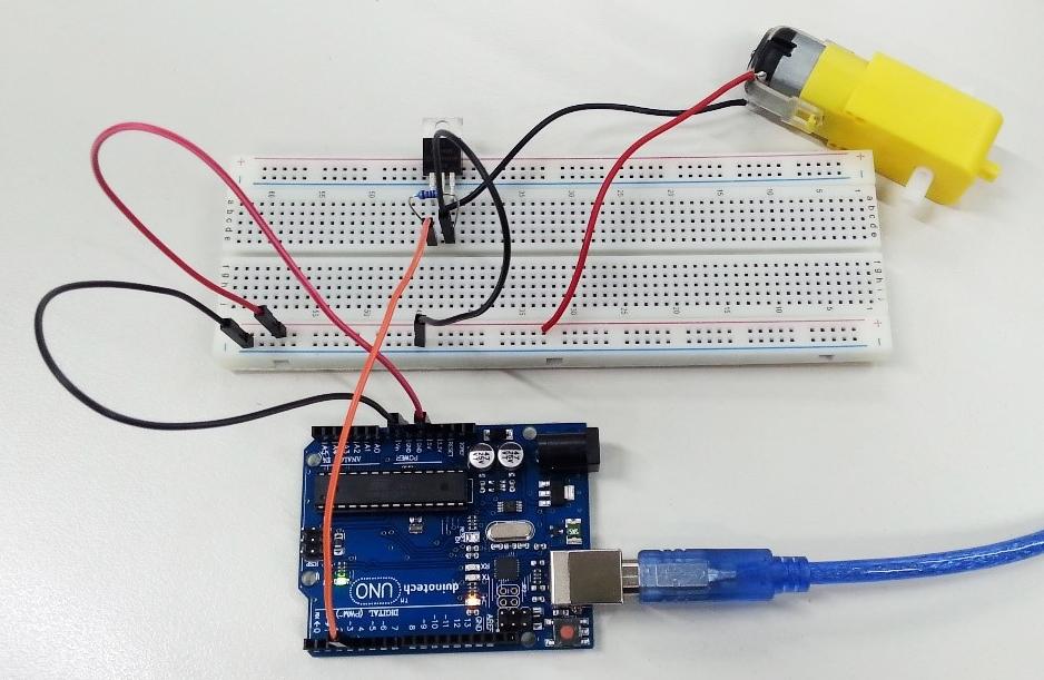
The below code will demonstrate how it works by turning the motor on and off.

1 void setup() {}
2
3 void loop() {
4 analogWrite(3,100);
5 delay(1000);
6 analogWrite(3,0);
7 delay(1000);
8 }

Another option for lower currents is to use a different type of transistor, called a bipolar transistor. Again, these come in two main types, NPN and PNP, with an NPN transistor typically being used as a low side switch. Discussing NPN transistors for now, while MOSFETs typically work off the voltage applied to their gate (compared with their source (VGS), a bipolar transistor depends on the current flowing into the base (and out of the emitter), and permits a proportional current to flow into the collector. The proportion is called the gain, and for a device like 

, this is around 100. Bipolar transistors are also more sensitive to voltage spikes (which can occur when a motor is turned off), so require a 'snubber' diode to shunt the spike away from the transistor.

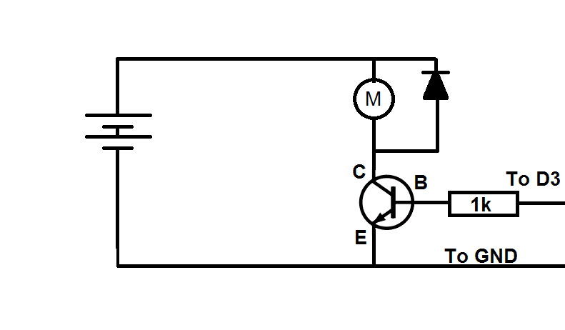
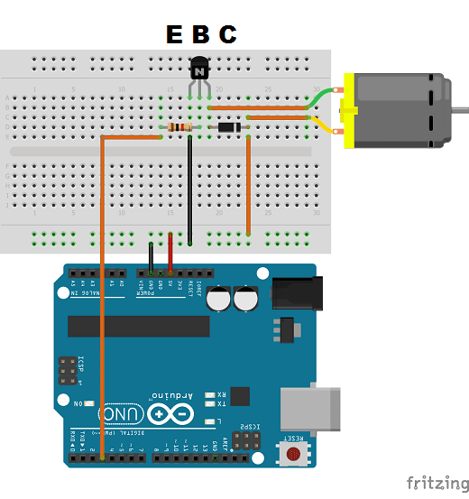
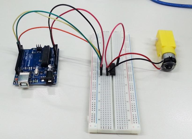
The same code as above will work with this circuit. You can see that the pins of a bipolar transistor also have different names- Collector, Base and Emitter. Like previously, this is a low-side driver. To create a high-side driver, you would use a PNP type such at 

.

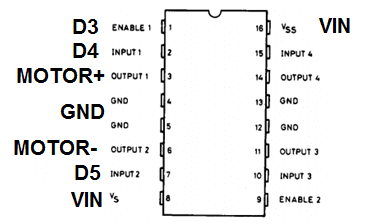
So you can see that for simplicity, a MOSFET requires one less component, and is generally capable of more current. These circuits are probably all you would need for a relay coil, or even a speaker generating tones, as the power only needs to be applied one way. If you need to reverse the current flow (for example, to reverse the direction of a motor), then you would need four transistors arranged in what is called a H-bridge. Instead of building this from parts, there are a couple of H-bridge IC's which make setting this up much easier, and removing the need for many external components.

What makes a reversible controller difficult is the need to combine a high-side driver and a low-side driver to be able to reverse the current. And this is even harder if the high-side voltage is more than the 5V the Arduino can handle.

Another thing that can occur is that if the two left switches (for example) were to be connected at the same time, the supply would be short circuited. Most H-Bridge IC's have circuitry to make sure this never happens, and also have inputs that can handle 5V signals from an Arduino while running off a higher supply voltage (like 12V). The 

 actually has two H bridges built in, and can run either two DC motors or even a single stepper motor. The 

 has two of these and control up to four DC motors. This H-Bridge IC can handle up to 36V supply voltage and up to 7V logic voltage, and has separate inputs for forward, reverse and enable. The Arduino pins marked below are the connections used in the demo circuit.

The below circuit can be used to demonstrate. Note that there are no external components at all. The IC even includes the snubber diodes to protect the internal transistors. You can see that the red wire is connected to the VIN pin, so that the motor can run from a higher voltage than 5V, such as a 9V battery.

The sketch below turns the motor forward for a second, off for a second and then reverse for a second and off for another second.

1 void setup() {
2 pinMode(4,OUTPUT);
3 digitalWrite(4,LOW);
4 pinMode(5,OUTPUT);
5 digitalWrite(5,LOW);
6 }
7
8 void loop() {
9 digitalWrite(4,LOW);
10 digitalWrite(5,HIGH);
11 analogWrite(3,150);
12 delay(1000);
13 analogWrite(3,0);
14 delay(1000);
15 digitalWrite(5,LOW);
16 digitalWrite(4,HIGH);
17 analogWrite(3,150);
18 delay(1000);
19 analogWrite(3,0);
20 delay(1000);
21 }

While it might look that the H-bridge IC is the much better solution, there are some limitations. If you need a very high frequency PWM, a transistor will usually be a better choice, as it can switch faster than a H-bridge. And of course, the transistor will generally be smaller and cheaper to implement, even with the extra components needed

Similar projects you may be interested in

Power
Bluetooth Power Point
Difficulty

Power
High Efficiency Power Supply
Difficulty

Power
Hand Gesture Power Socket
Difficulty

Power
LoRa Remote Relay
Difficulty