LoRa Remote Relay
Summary
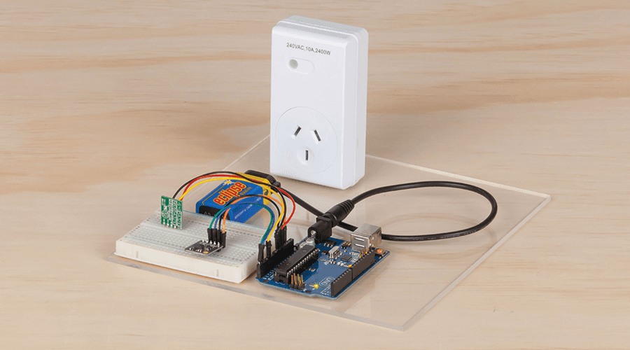
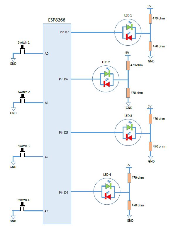
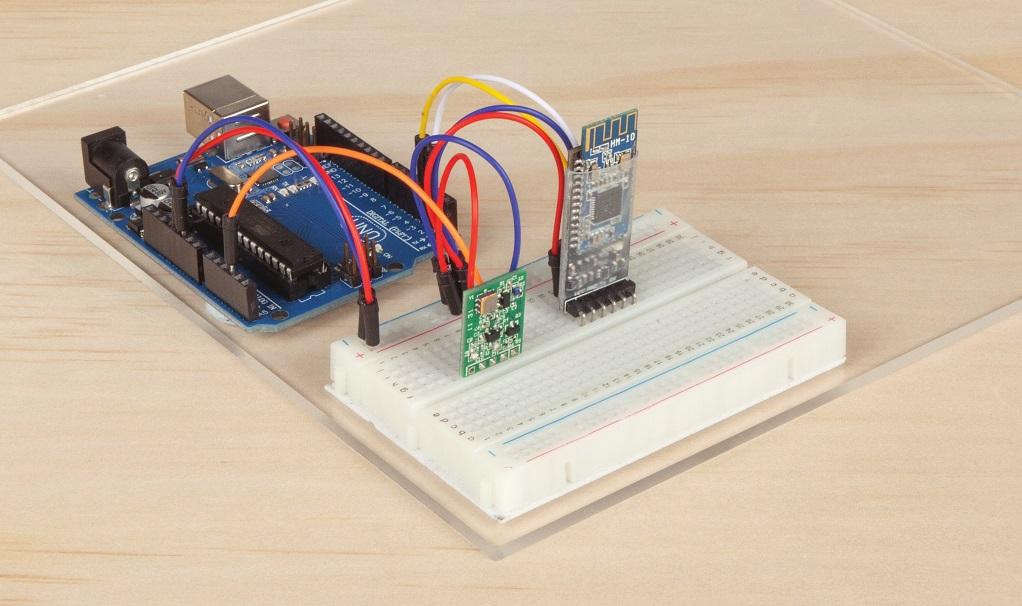
We are very excited to get the chance to play with our new LoRa Shields, and test just how far we could get a signal using LoRa technology. With one of our tests, we were able to get a signal to travel about 200m, including through the corrugated iron of the warehouse and the concrete office building. We set about building a practical project that would make best use of the technology. The LoRa Remote Relay is basic- four buttons at one end and four relays at the other end. It also has LED's next to the buttons, so unlike other remote relay systems, there is feedback that the relays are operating as commanded.
Materials Required
| 2 | Duinotech UNO r3 Main Board | XC4410 |
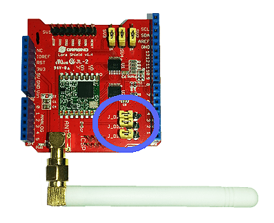
| 2 | Arduino Compatible Long Range LoRa Shield | XC4392 |
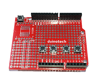
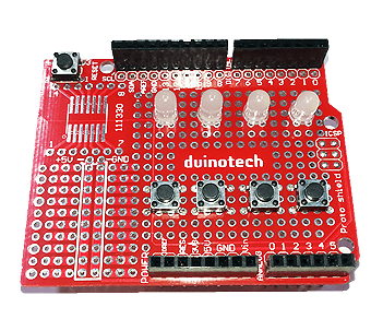
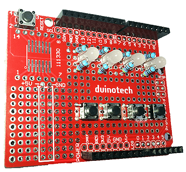
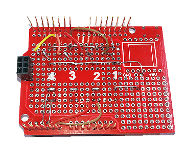
| 1 | Duinotech Arduino Compatible Prototyping Shield | XC4482 |
| 4 | 1.4mm SPST Micro Tactile Switch | SP0601 |
| 1 | 470 Ohm 0.5 Watt Metal Film Resistors - Pack of 8 | RR0564 |
| 4 | Bicolour Red/Green 5mm LED 45mcd Round Diffused | ZD0250 |
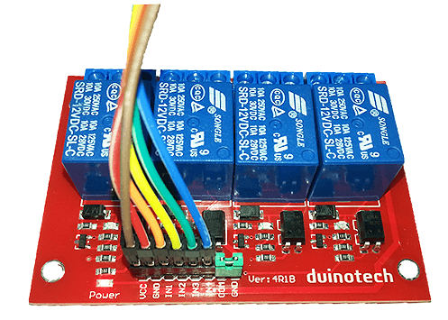
| 1 | Arduino Compatible 4 Channel 12V Relay Module | XC4440 |
| 1 | 150mm Plug to Socket Jumper Leads - 40 Pieces | WC6028 |
Table of Contents
Future Improvements
The success of a project like this is using it in a real world application. We've heard of a few people using remote relays to control motorised gates. The advantage of the LoRa Remote Relay in this case is that the actual position of the gate could also be monitored and fed back to the transmitter unit, so that you could not only know that the motors are working, but that the gate has reached its endpoint. Or you could use it for remote pump operation, and also feed the data about tanks levels back to the user.
Similar projects you may be interested in
.jpg%3Fbranch%3Dprod&w=1080&q=75)