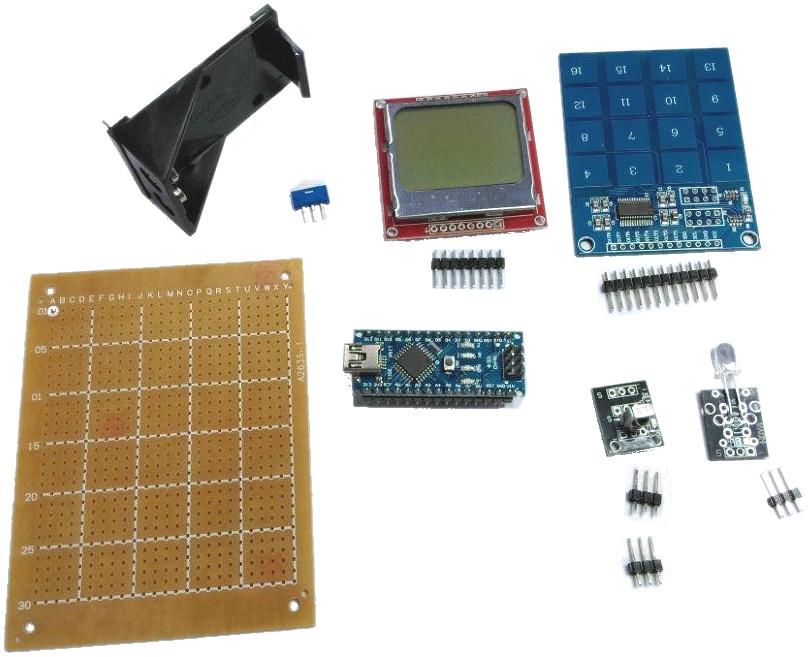
First step is to remove the header pins from all components (except for nano) as we'll be re-arranging the layout. Also snip header pins where needed, with 2 lots of 3 for the IR sensor (just for a bit of strength).
As the battery has to be connected on the underside "solder pad" side, there's a bit of a trick to mount the battery holder.What we're aiming to do is to make a bit of copper on the top side of the board for the battery connector to solder to.
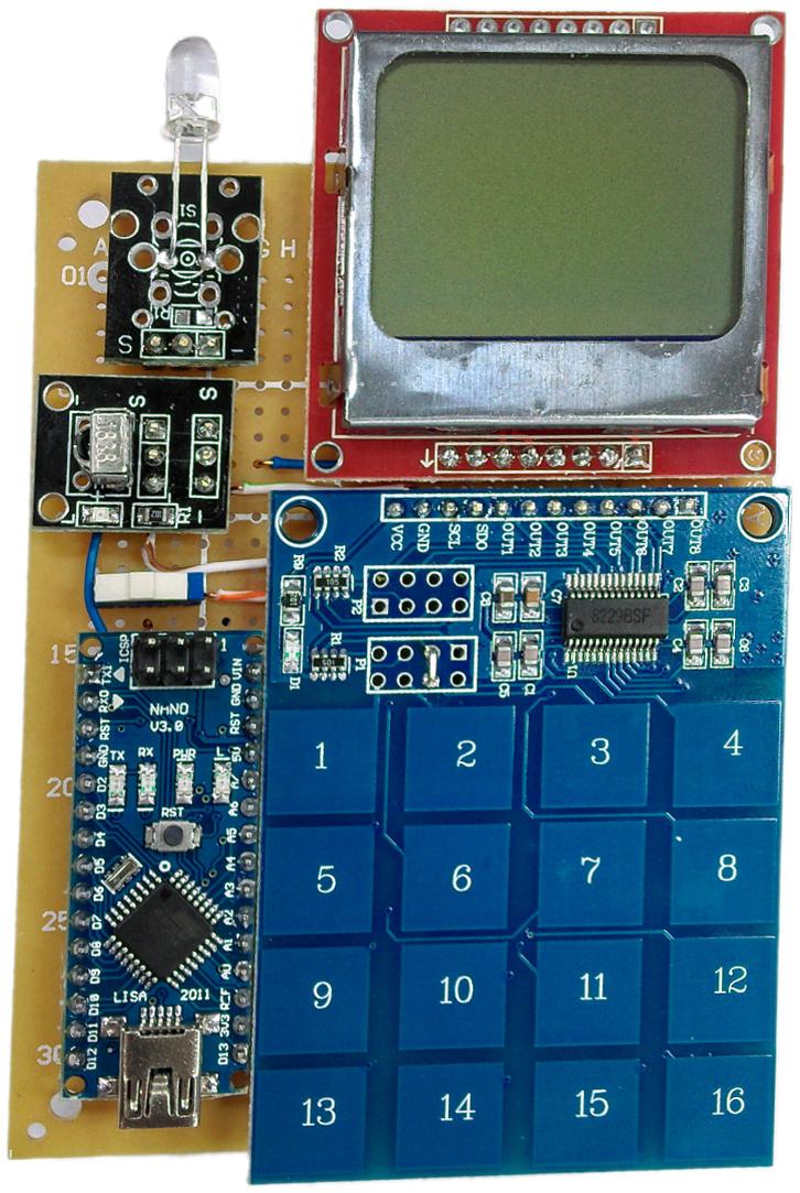
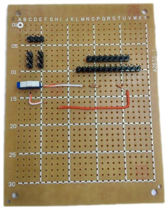
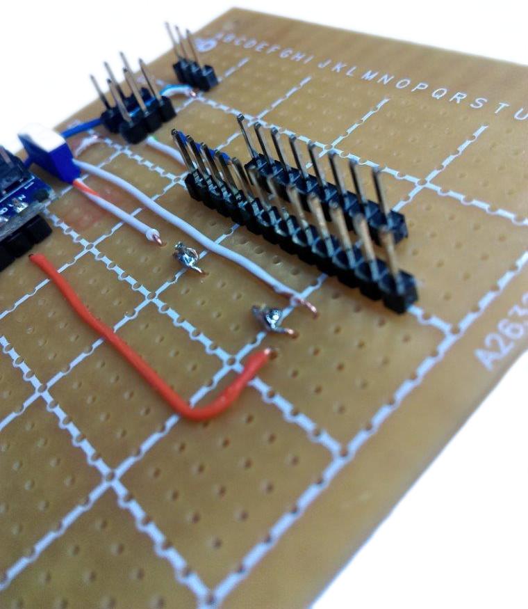
Firstly: begin with the end in mind:
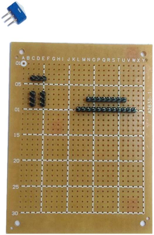
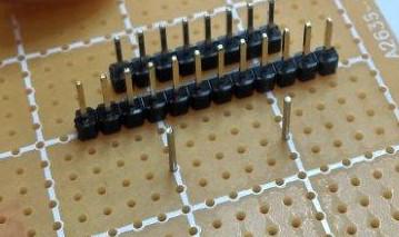
Snip and place header row connections as shown above.
Place the battery holder where you want it. I opted to place the power pins along row 13.
Right next to this, we'll place about 4cm of stripped copper wire from the ethernet cable in the hole next to it and solder that into place (remove the battery pack to solder).
Wrap around and place into the hole on the other side of the battery connector:
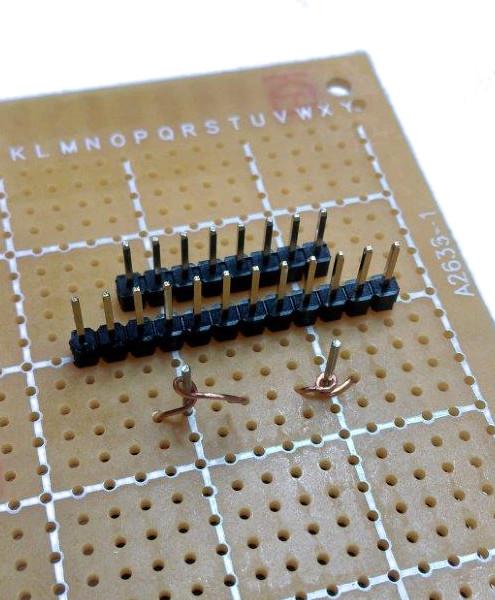
When you poke the wire through the other side, place the battery holder back in place and pull on the wires, so that the loop can get tight and flush against the legs.
Remove the battery connector and solder in place without disturbing the copper wire, you should get something like this on the top side of your board:
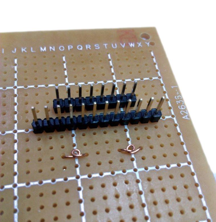
Now when we're ready to put the battery holder back in, it should slide into the copper loops easily.
Now we'll start putting in the major power rails. Notice that the 9V battery will connect to the VIN pin of the Nano, and everything else will be powered off the 5V pin.
With the battery holder on the underside, this means the left leg of the battery holder (from the top) is the positive 9V. take this to the micro power switch as below:
Then the middle pin of the switch goes to F16 (with G16 corresponding to VIN of nano)
The Battery negative terminal can just go to H17 (G17 corresponds to ground on nano)
Also connect the positive and negative rails from the sensors to where the nano is going.
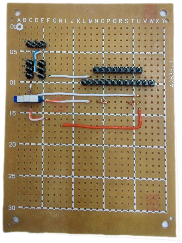
F9 - M9 connects screen GND to IR receiver ground
E5 - D9 connects IR transmitter ground to IR receiver ground
C10 - U12 connects IR receiver ground to Battery Negative terminal.
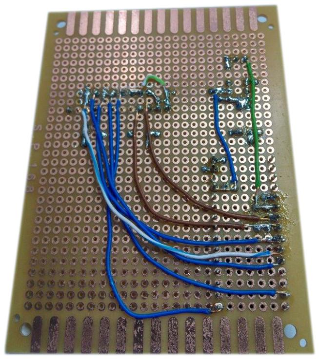
Notice in the next picture:
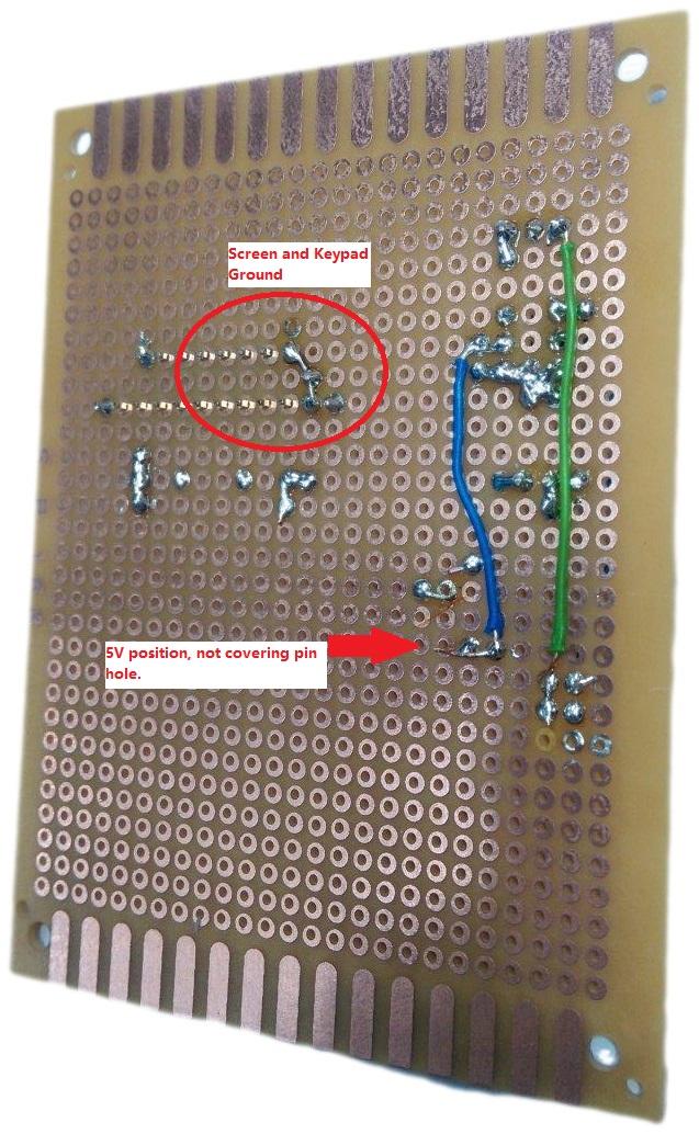
M9 connects to a bridge between the screen and keypad ground, N8 & M10
E10 (or F10) joins down to E19 - this will be next to the 5V pin on the nano. (G19)
There is also the green wire from C4 to C21 -- this will be bridged to A21 which is D3 on the NANO
You can end the wire on any of the pads around the pin that you want, just as long as you don't cover the hole so the arduino nano can pop through and connect.
On the top side, you can place the B7 to B20 wire which will connect the receiver to D2, and the L8 to G8 wire, which will connect the +5v between the sensor, screen and keypad.
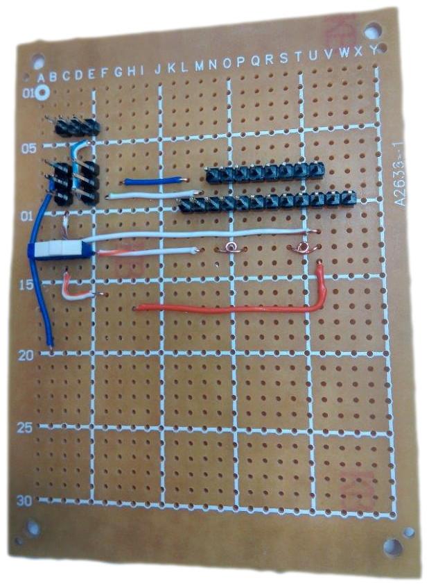
The rest of the connections can be a bit of a mess but I'll try to go through them one by one so that we can tick them off as we go.
Place in the arduino in the lower corner of the board, you should find that the pins themselves will keep it in place and you shouldn't have to pre-emptively solder it. Make sure the VIN and GND connections are proper while you're at it and rework them if needed.
Make the following connections.
Bridge a connection between L8, L10, O8 and O9
SCL N10 connects to A22 (which is D4 on Nano)
SDO M10 connects to A23 (which is D5 on Nano)
CLK Q8 connects to G30 (which is D13 on Nano)
DIN R8 connects to A29 (which is D11 on Nano)
DC S8 connects to A24 (which is D6 on Nano)
SCE T8 connects to A26 (which is D8 on Nano)
RST U8 connects to A25 (which is D7 on Nano)
Now we can mount components. First step is to mount the battery holder to hide that jumble of wires. Poke it through and solder from the topside of the board, then snip the leads so it is as small as possible.
Then mount the keypad to the long row of headers, and snip them down so you can solder the screen in place as well.Mount the receiver going across the two sets of 3pin headers, and the transmitter on the top row.