High Efficiency Power Supply
Difficulty
Power
Summary
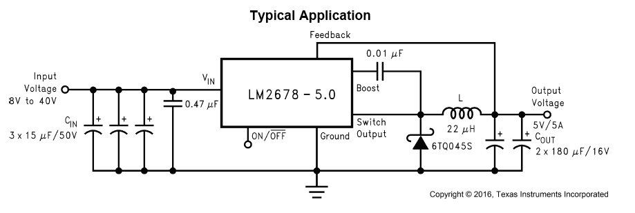
Learn the basics of electronics in making this high efficiency 5V power supply. Using the professional standard LM2678 5V step down ( or "buck" ) regulator, we can design a power supply that takes any voltage between 5-37 and bring it down to a constant and stable 5V rail. perfect for use in your projects. You will also learn the basics of how to read and understand datasheets.
Materials Required
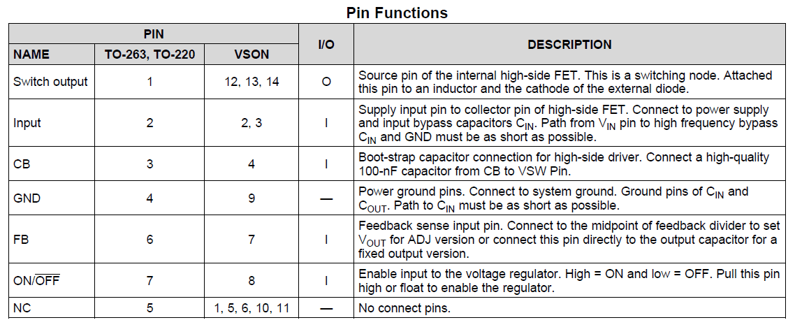
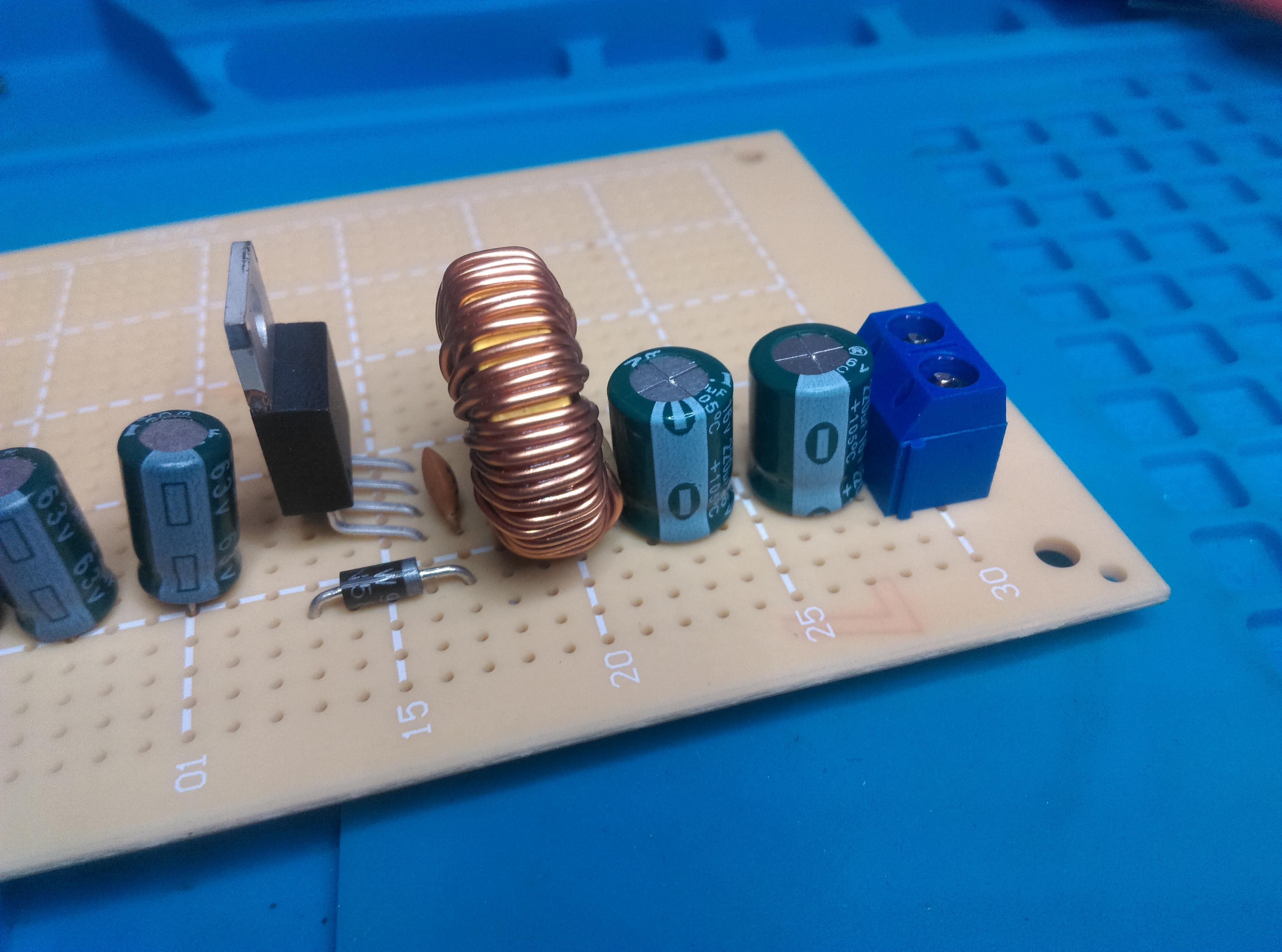
| 1 | Voltage Regulator LM2678T-5 +5V step-down 5A TO-220-7 | ZV1636 |
| 3 | 22uF 63VDC Low ESR Electrolytic Capacitor | RE6342 |
| 1 | 0.47unF 50VDC Monolithic Capacitor | RC5498 |
| 1 | 10nF 50VDC Ceramic Capacitors - Pack of 2 | RC5348 |
| 2 | 220uF 16VDC Low ESR Electrolytic Capacitor | RE6312 |
| 1 | 100uH 3A Prewound Ferrite Choke | LF1272 |
| 1 | 1N5819 Schottky Diode - 40V 1A DO41 | ZR1020 |
| 2 | 2 Way PCB Mount Screw Terminals 5mm Pitch | HM3172 |
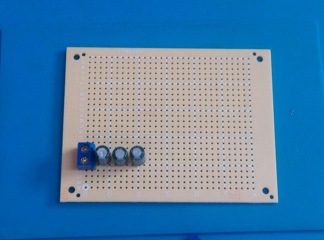
| 1 | Universal Pre-Punched Experimenters Board - Small | HP9550 |
Table of Contents
- Checking the datasheet
- Confirming the specification
- Selecting the components
- Laying out the PCB board
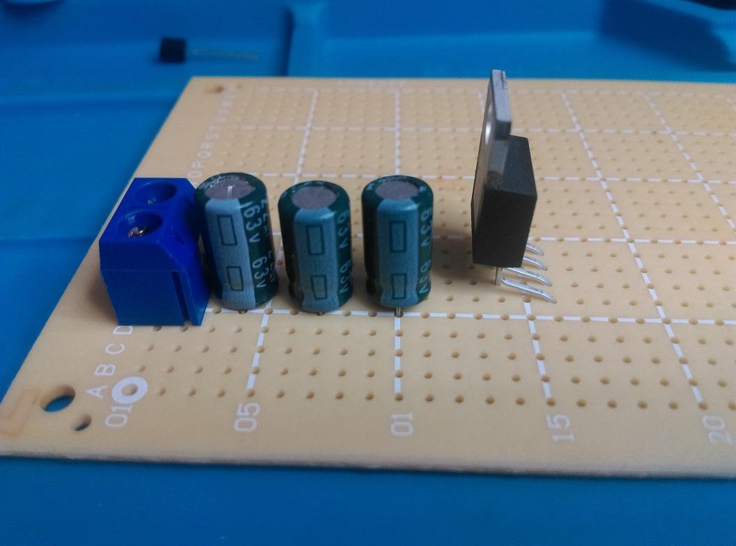
- Step 1: Position the starting terminal and input capacitors
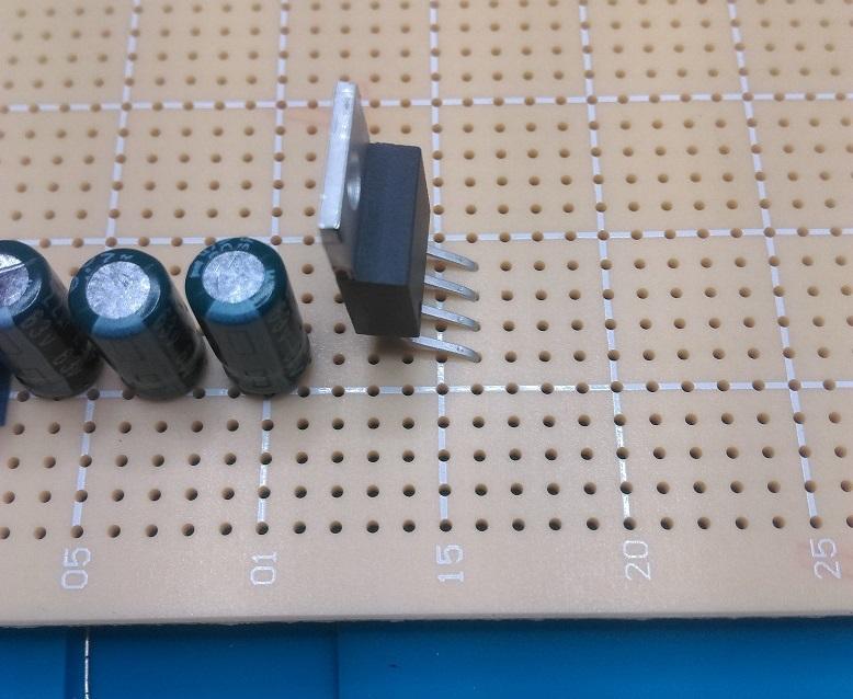
- Step 2: Place regulator
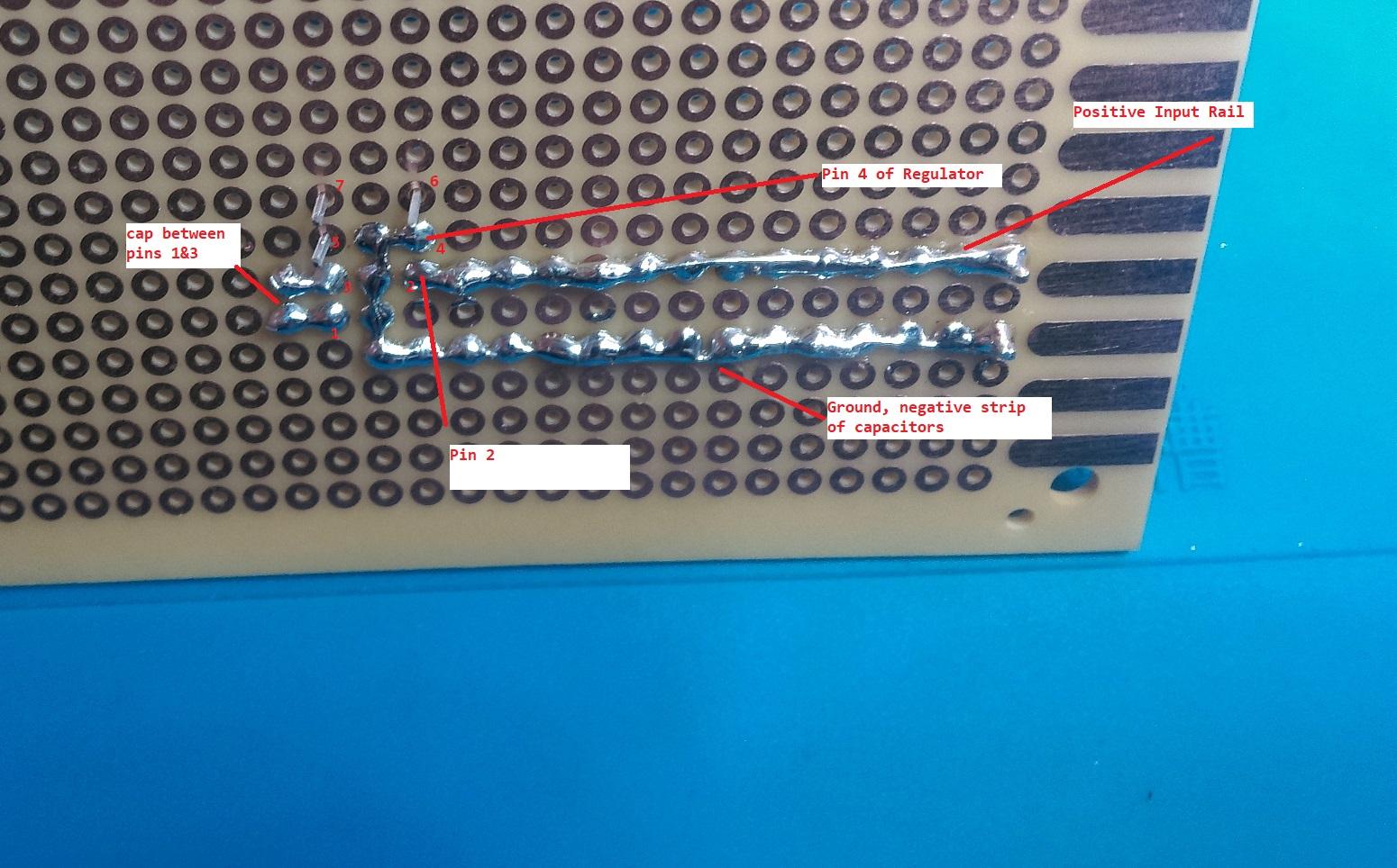
- Step 3: Solder into place.
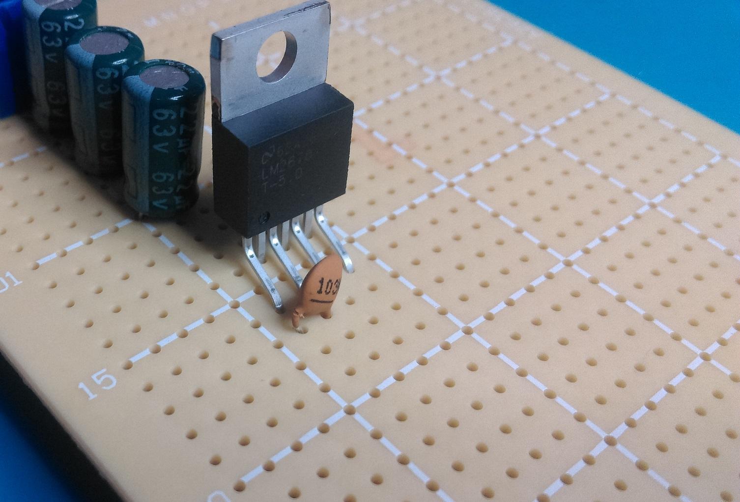
- Step 4: Place Regulator components
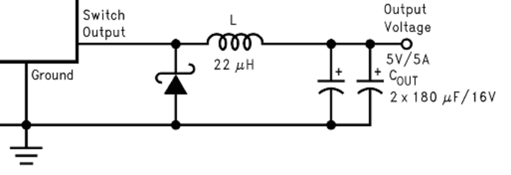
- Step 5: Output components and final soldering
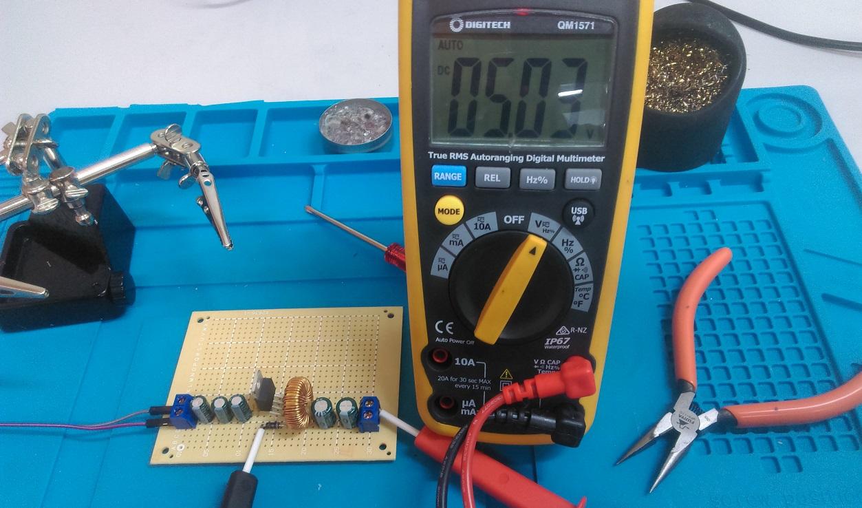
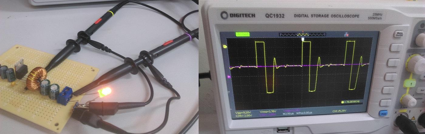
- Final test and use

.jpg%3Fbranch%3Dprod&w=1080&q=75)
.jpg%3Fbranch%3Dprod&w=3840&q=75)

Similar projects you may be interested in