This project has two main parts, the main unit and the controllers (four of them)
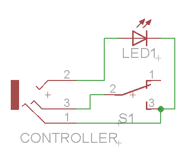
The Controller is a relatively simple set up, you are connecting the arcade button's switch and LED to the socket connector for the cable to connect to.
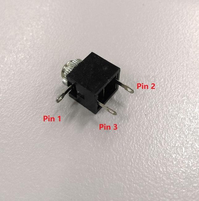
Pin 1 is the ground connection, with pin 2 being the +5V coming in, and pin 3 is the switch connection back to the main unit.
If you want, you can solder the connections and make sure that the unit works before assembling it into a case.
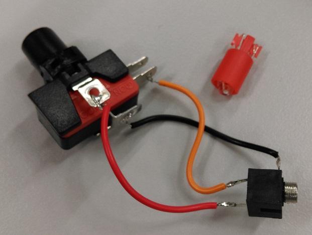
1. You'll notice that once you place the switch in the switch housing (connect the shorter pin in first, then swing the rest of the switch in so the taller pin can clip in) you will have two wings out the side of the switch. these are for the LED. Connect Pin 2 of the connector to one of them, and connect the other to the bottom pin of the switch (COM - for "Common")
2. Then connect the NO pin of the switch (middle pin of the 3, should be marked "NO") to Pin 3 of the socket connector, and connect COM to Pin 1.
You should now have something that looks like this:
3. In terms of the case, you drill a 5mm hole on one side for the socket connector, and a larger 45mm hole for the button to fit through.
With the case as chosen, I wasn't able to fit the thread screw onto it while it is still in the case, so I went without the screw and used some super-glue instead.
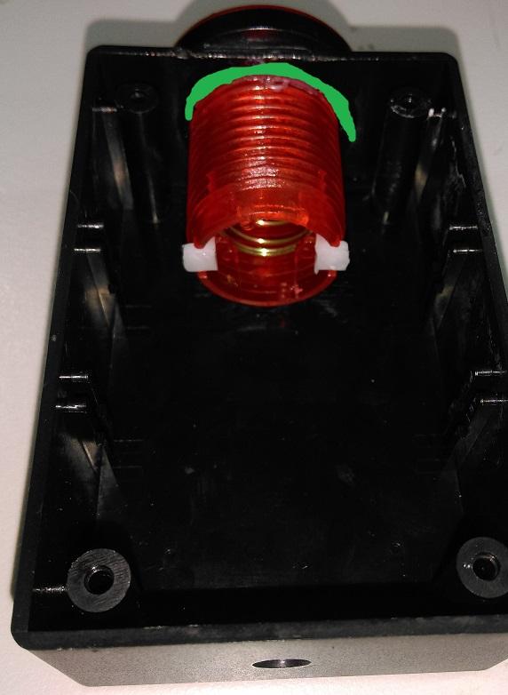
Drill out the hole and place the switch housing in. you'd probably want to use super glue up around where the green is in the picture. There is a little bit of overhang but it's not a big concern
4. Then just place the unit in the housing, clip into the button assembly and mount the socket sticking out of the other end
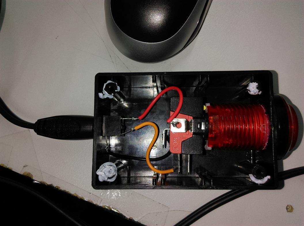
One controller finished, 3 more to go
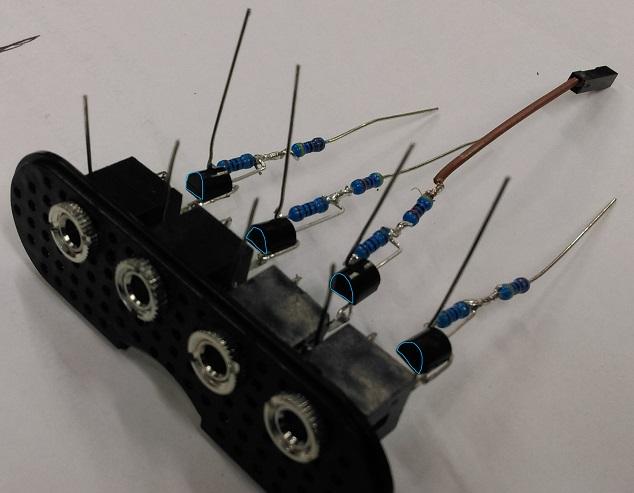
Here is where the tricky part is. you're going to make 4x of the same part for each of the controllers, and there's not a lot of room in the case, but it is doable.
If you want to provide your own case, feel free to do so and use the schematic above. These instructions below are to get it fitting into the tiny XC9002 case, but if you have more room to play you won't have to be so tight.
Scroll down further for the finished look if you want to start with the end in mind.
Notice that there is a resistor between the collector and the base pin. This can be confusing below, but look at the diagrams and pinouts to ensure that you have the connections right, especially if you have never played around with transistors before.
.png%3Fbranch%3Dprod&w=1920&q=75)
1. Start by twisting two resistors together, one from each pack, and place a neat blob of solder to join them together like such:
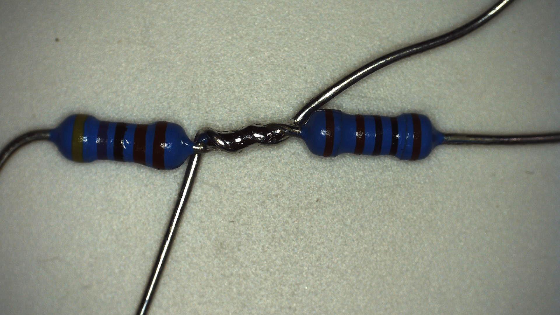
Note, in my prototype, I used 1k and 4k7 valued resistors. you will find that the values are fairly similar for voltage dividing purposes.
Clip the offshoots of the twist and keep them aside for later.
Recall the pinout of the transistors:
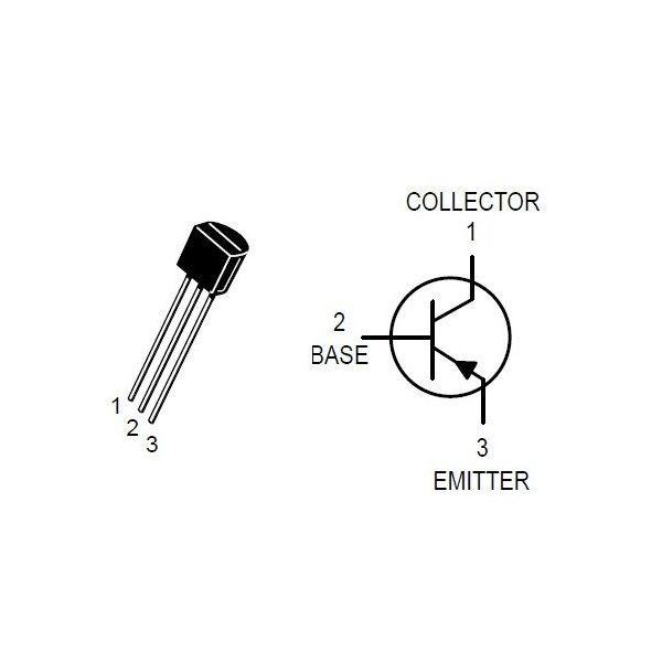
Note, this isn't the same for every transistor, but most of them should be similar
Looking at the face of the transistor, left to right, you have the collector, base, and then emitter.
2. bend the collector at a 90deg right angle so that it is fanning out to the left, same for the emitter.
3. Then place the resistors near the collector so that the smaller valued resistor (2.7k) can lay alongside the base pin, and wrap around the collector pin so that it can be soldered and then clipped off. Bend the bottom of the base pin to connect to the join of the two resistors. Refer to picture:
![]()
![]()
The red in this diagram highlights how the emitter pin was bent before clipping off the excess
5. Finally, bend Pin 1 of the socket connector close to the body of the socket, so that you can fit multiple units in.
That is now 1 single unit. Do 3 more times.
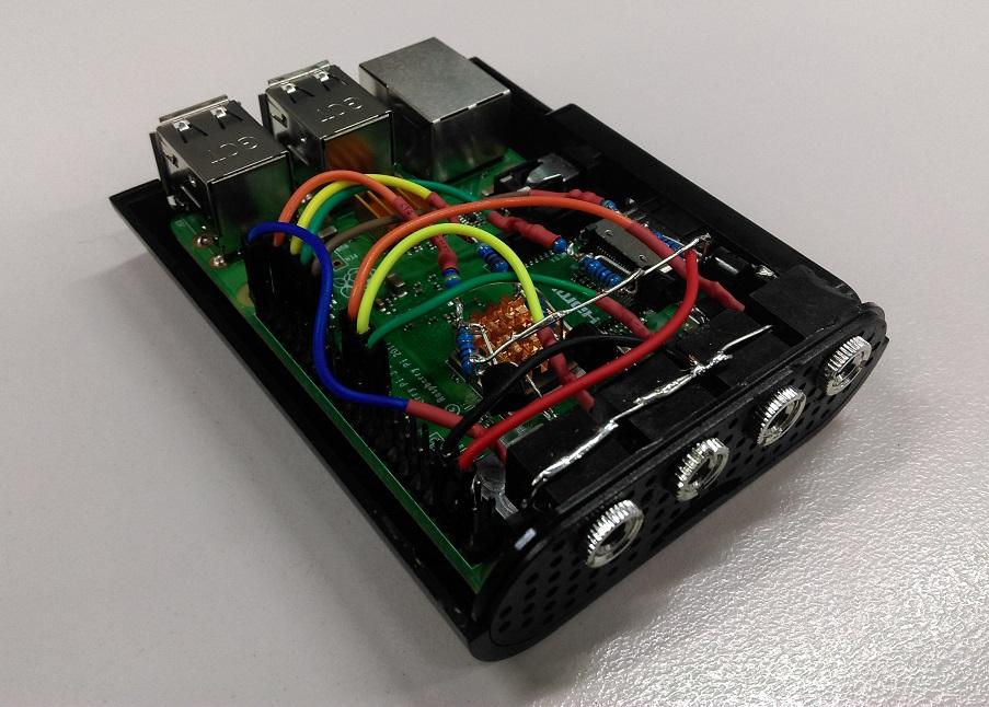
It is a tight fit, but entirely possible to fit the 4 socket connectors as well as the circuitry into the tiny XC9002 case.
First step is to drill out the spaces from the front-grill. Here we've marked the places to drill (in red):

Make sure you're looking at the correct side of the front grill. you'll notice there is a little notch where they give space so you can pull out the SD card of the assembled unit.
With the rightmost hole, I have marked (in orange) an alternative position, which would make for closing the case easier, however the circuitry will be closer to the HDMI socket and so you will have to isolate and make sure that the circuits do not touch by using electrical tape or similar.
Drill out the holes, then attach the 4 socket units:
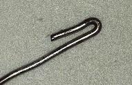
Here, we have also attached a small hook to each of the pin 1 of the socket connectors as I attached them, so that we can bridge these connections later. these were from the small resistor leads that we clipped back when we attached the two resistors together.
Finally, connect all the Pin 1 leads together, and all the collector leads together, so you get something that looks like the following:

You now have finished your front grill assembly.Cut up some female jumper leads or similar so that you can connect to the rPi GPIO header connector.
The end of each resistor lead is the output to the LED for the controllers, and the unconnected Pin 3 of each socket adapter is the input from the switch. Using some heat shrink at this point is also a good idea as it keeps things mechanically secure and electrically isolated.
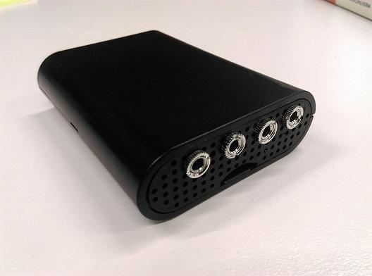
Our final unit looks something like this, with heat-shrink attached:
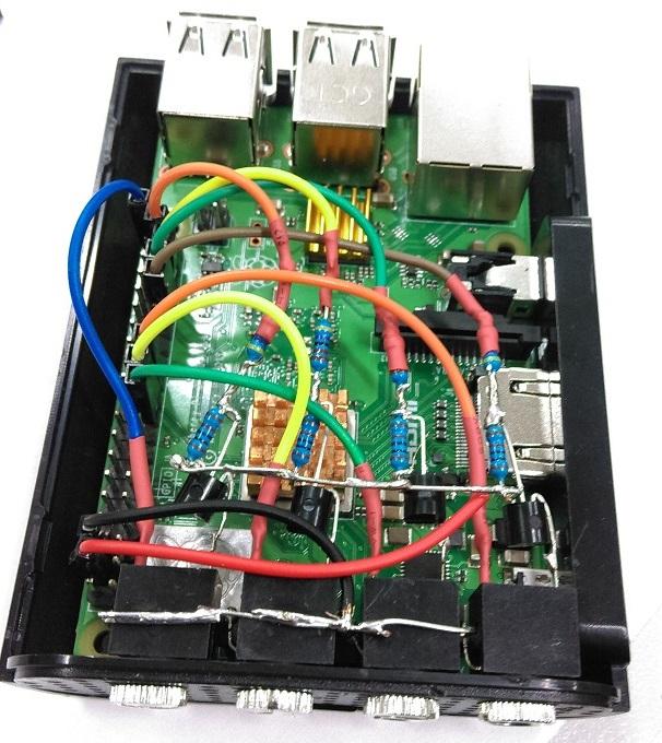
This is our pin-out, you can deviate from this if you want, but you'll have to change the code in config.py
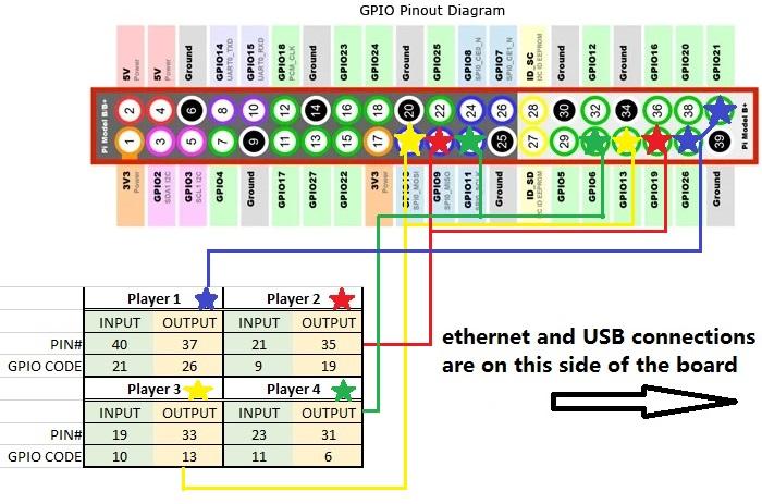
1 #set these to the GPIO pins, in order of player 1,2,3,4:
2 button_pins = [21,9,10,11] #Input button pins
3 led_pins = [26,19,13,6] #Output LED pins
4 '''
5 the idea would be, if the led and buttons are in the form of
6 [a,b,c,d]
7 [e,f,g,h]
8 the zip function will bring it to:
9 [
10 (LED(a), Button(e)),
11 (LED(b), Button(f)),
12 ... ]
13 '''
14 players = list(zip([LED(l) for l in led_pins],
15 [Button(b) for b in button_pins]))
Making it fit in the case
The only final issue now is getting the whole thing in the case. Unfortunately, with having 4 controller ports, the final port is blocking one of the support beams holding down the case. Use a pair of side-cutters and trim down the beam so that it's almost as flush as the case.
At this point you will be able to try and fit the case together, first by putting the rPi in the base, and sitting the front-grill in on top. Connect the header pins to where you want them, and sit the roof of the case on top. you should be able to screw in the 3 remaining supports and depending on how neat everything is, you should have a pretty neat little unit.