Progress Bar

Skip to main content

Jaycar
...

GPS World Clock

GPS World Clock

Difficulty
Test & Tools

Summary

While most phones have the ability to display the local time throughout the world, you may not always have access to an internet connection. With our World Clock, all you need is a GPS signal.


Materials Required

1Rotary Encoder Switch with PushbuttonSR1230
1Arduino Compatible 128x64 Dot Matrix LCD Display ModuleXC4617
1Duinotech MEGA 2560 r3 Main BoardXC4420
1Arduino Compatible GPS RCVR Receiver ModuleXC3712
1150mm Plug to Socket Jumper Leads - 40 PiecesWC6028
1M3 x 15mm Steel Screws - Pack of 25HP0406
1M3 Steel Nuts - Pack of 25HP0425
13mm Nylon Washers - Pack of 10HP0148
1Jiffy Box - Black - 158 x 95 x 53mmHB6011
1100nF 50VDC Ceramic Capacitors - Pack of 2RC5360

Table of Contents

We have provided a cutout file for both of our projects this month, so feel free to print out (or, if you're very nice, you can ask the store to print out for you) a cutout sheet, and use some cheap glue to keep the paper in place while you drill and cut into the Jiffy enclosures. This will help get the sizes just right.

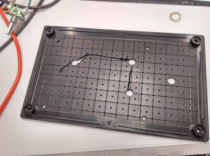
There's not a lot of work for this project, the main concerns are related to cutting out the jiffy box. Use the cut-outs to help get the sizes just right, then drill out the corners and slide in either some sort of band-saw or nibbler.

While we haven't used it, we've heard post-humorously that the 

 is great for this, and we'll be trying it next time we're modifying a Jiffy box.

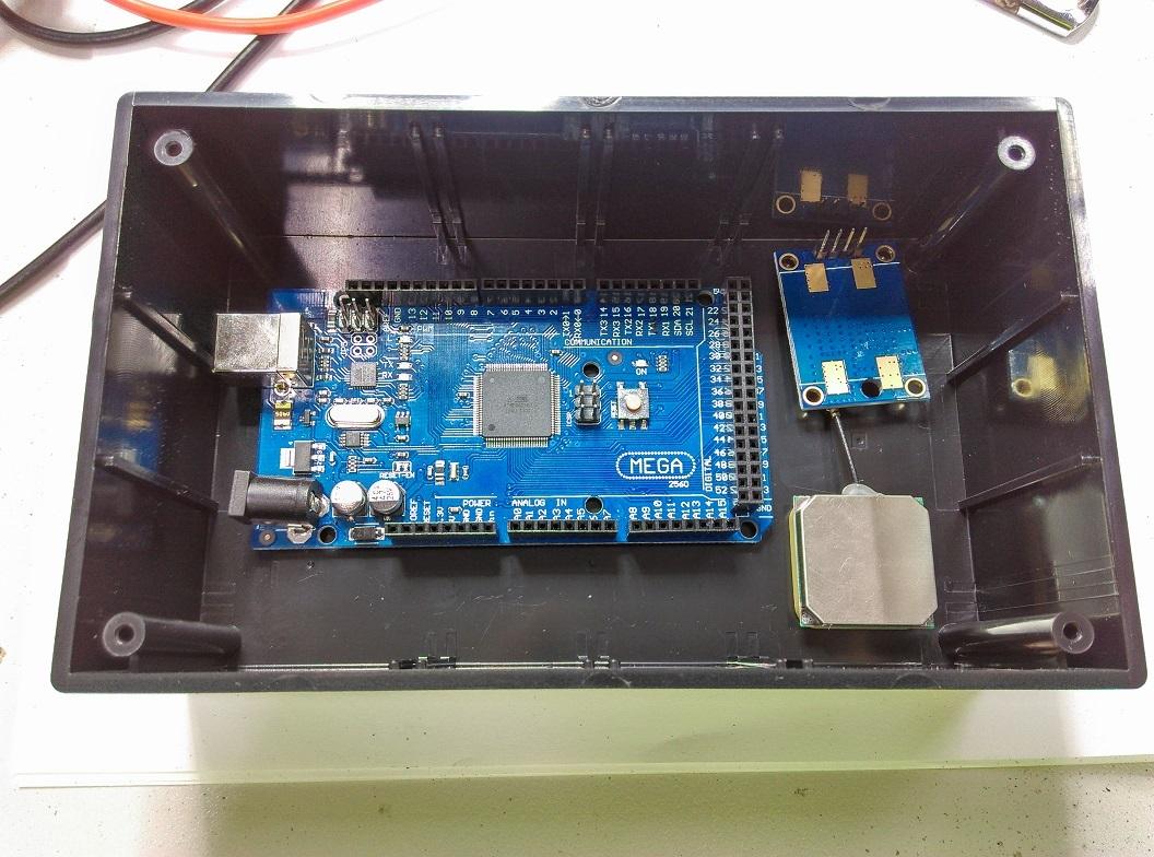
Position where you want, We've opted to have the mega and GPS in the enclosure, with the screen and encoder mounted on the front panel, as shown.

The GPS is mounted face down so we don't have to change the pins, and we just use the jumper leads to connect the modules to each other. At this point you'd probably want to drill out the 3mm holes and use some nuts and bolts to mount everything to the back of the case. Don't use the washers under the mega or GPS, as you'll need to use them for mounting the LCD panel. You could use some hot glue to glue down the GPS antenna.

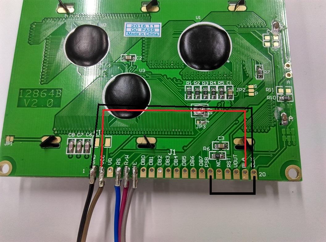
The LCD Panel does need jumper wires connecting 5V to BLA and GND to BLK as shown; also solder PSB to ground so that it is always enabled.

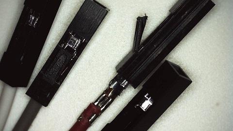
You can use a small pin or screwdriver to get in under the plastic of the sockets for the leads, and easily slide off the plastic.

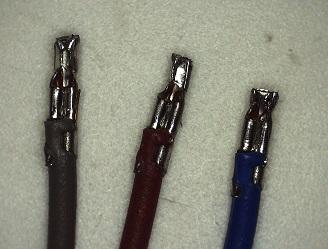
This will make for easy and neat soldering onto other components such as the encoder, and you can snip them to be a suitable size to mount onto the screen.

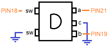
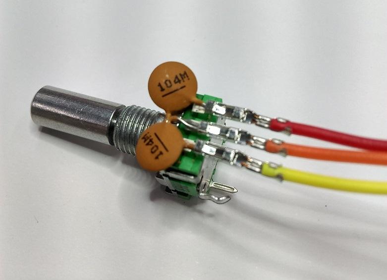
The encoder will need the two capacitors connected to it so that they can absorb the 

 and makes for a very smooth experience with the encoder. Attach these between pins A-C and B-C on the encoder. You can see the pinout diagram for the encoder below.

It will be easier if you first put on the sockets from before, then poke in the capacitor legs so that they all fit snug and tight, then apply a small dab of solder to join them all together.

The encoder requires a 10mm hole in the front case.

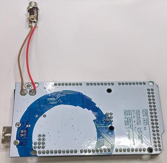
We've also soldered the DC jack to the DC jack on the MEGA, so that they can use the same regulator and have the reverse polarity protection. If you opt to use the DC Jack, ensure that the center pin is the positive (red) and the outside is negative (brown).

If you don't want to use a DC Jack, you can simply cut out a square hole for the MEGA's USB Connection.

We opted not to include the Knob for this project, as we'll allow you to choose whatever you want. The knob in the picture is 

. But we have other styles and sizes for you to choose.

We're using pin interrupts on 19 and 21 to calculate the rotary encoder values by counting the number of turns since we last processed it. This allows for a very fluid response on the screen, even with lag or time delays.

//change to PIN_A for opposite directionattachInterrupt(digitalPinToInterrupt(PIN_B), isr_enc,CHANGE);void isr_enc(){ //interrupt service routine if(digitalRead(PIN_A) == digitalRead(PIN_B)) enc_value++; else enc_value--;}

We've defined a LOCAL_TIME constant for you to set in the code for a simple localtime adjustment

#define LOCAL_HOURS 10#define LOCAL_MINUTES 0

We also create our own struct to hold Timezone information, such as the name, code, GPS-coords, and adjustments.

struct tzinfo { const char* name; const char* tz; long latmin; long latmax; //GPS coords long lonmin; long lonmax; short hours; //adjustments};/*because an hour adjustment can only be up to 12,which is the first nibble of a byte, we can use the othernibble to act as flags for parameters such asHALF, DST, or negative times*/#define TZ_HALF 0b10000000#define TZ_NEG 0b01000000#define TZ_DST 0b00100000struct tzinfo tz_list[] = { {"Brisbane", "AEST", -25900761,-28120489, 137913970,153451528, 10}, {"Sydney", "AEDT", -25900761,-28120489, 137913970,153451528, 10 | TZ_DST}, {"Adelaide", "ACDT", -25900761,-28120489, 137913970,153451528, 9 | TZ_DST | TZ_HALF },}

Once the code is uploaded it should be easy enough to use, it will find the GPS and UTC time, and automatically apply a +10 timezone conversion to it. LOCAL_TIME is configured in the code, and the selected timezone is selected through the menu system, by pressing on the encoder wheel.

If time is not changing, try taking it close to a window so that it can get a better lock on the GPS signal. You should be able to see some output on the Serial Monitor if you connect it to your computer. if you see a lot of empty fields (,,,,,) then you might have a problem getting a GPS signal.

Similar projects you may be interested in

Portable Soil Moisture Meter
Test & Tools
Portable Soil moisture meter
Difficulty

Test & Tools
Wireless Garden Monitor
Difficulty

Arduino Based LED Tester
Test & Tools
Arduino Based LED Tester
Difficulty

Test & Tools
IoT Smart Wireless Switch
Difficulty