Progress Bar

Skip to main content

Jaycar
...

Duinotech Game Machine

Duinotech Game Machine

Difficulty
Entertainment

Summary

We found a little game project online at http://gamebuino.com, and with it being open-source, realised we could make our own version of it using duinotech parts. Even better, there's already a heap of games that have been created at https://github.com/Rodot/Gamebuino-Games-Compilation, and because it's based on Arduino, you can create your own games as well. There's a complete set of libraries for making your own games at https://github.com/Rodot/Gamebuino, too. And just to make sure you've got something to get started with, we've built a Tic-Tac-Toe game for it too.

Materials Required

1Arduino Compatible Nano BoardXC4414
1Arduino Compatible 84x48 Dot Matrix LCD Display ModuleXC4616
1Duinotech Arduino Compatible Active Buzzer ModuleXC4424
71.4mm SPST Micro Tactile SwitchSP0601
1Universal Pre-Punched Experimenters Board - SmallHP9550
110k Ohm 0.5 Watt Metal Film Resistors - Pack of 8RR0596
14.7k Ohm 0.5 Watt Metal Film Resistors - Pack of 8RR0588
1Rainbow Cable 16 Core - Sold per metreWM4516
128 Pin Header Terminal StripHM3211

You'll notice that the Prototype Board has numbers and letters marked on the columns and rows- we need to line up the components with the coordinates given so that we can fit them all in. We'll fit all the components first, then join them together with wires later.

Insert the Pushbuttons as follows:

Note that the buttons on the left should their legs running along the lettered columns (left to right)

Button

Rows

Columns

UP

24 and 27

P and R

DOWN

24 and 27

V and X

LEFT

27 and 30

S and U

RIGHT

21 and 24

S and U

C

24 and 27

H and J

Buttons on the right should have their legs running along the numbered rows (up and down).

Button

Rows

Columns

A

1 and 3

V and Y

B

1 and 3

R and U

Make sure the buttons are pushed down firmly against the Prototype Board, and then solder them down. Take six of the 4.7kOhm resistors and for each of rows 13-18, put a resistor from column L to column P, and solder them down and trim the legs. Then take six of the 10kOhm resistors and for the same rows, put a resistor from column Q to column T. Before cutting the legs off, join all of the resistor legs on column T together by bending one of the legs over and soldering. Also join each pair of resistors by soldering the legs in column P to the leg in the same row to the leg in column Q, and then trim the excess.

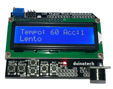
After the buttons and resistors are installed, the board should look like this:

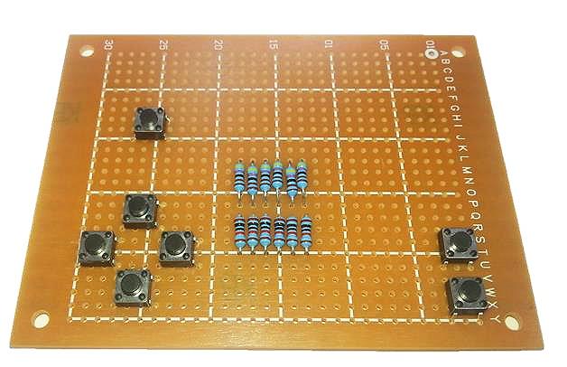
Note the leg positions of the switches

Note the joins along column T and between P and Q

Next, take the Header Strip, and break off a row of eight pins. Place this in Column I, rows 9-16, and then fit the LCD Screen into Column Y, rows 9-16. The header pins should go into the holes in the top of the LCD Screen. Solder these pieces down, leaving a small gap between the resistors and the LCD Screen so they don't touch.

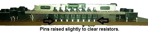
Note that the top of the screen has a broad silver border. After this, you can trim the pins at the back of the LCD Screen so they aren't so long.

The next step is to fit the Nano onto the board. This goes into columns A and G, from row eight to row 22, with the USB connector facing above the side of the board with five buttons. The Nano can be pushed down firmly onto the board and soldered into place.

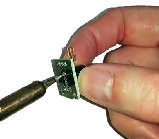
The final component on the front side of the board is the Buzzer. For this, we remove the Buzzer unit from the module, so that we can make our final board as compact as possible. The can be done by applying heat from a soldering iron to each of the legs (you may need to go back and forth between the legs a few times) while slowly pushing the Buzzer off the board. Be careful that it doesn't fly off as the last of the solder gives way.

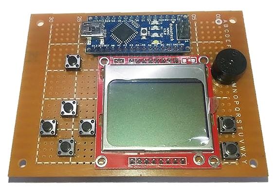
The Buzzer unit can now be installed on the board- the positive pin goes to hole I1, and the negative pin to L1. You will probably need to pull the sticker off the Buzzer to see the markings, and usually, only the positive pin is marked. From the front, our Arduino Game Machine should look complete:

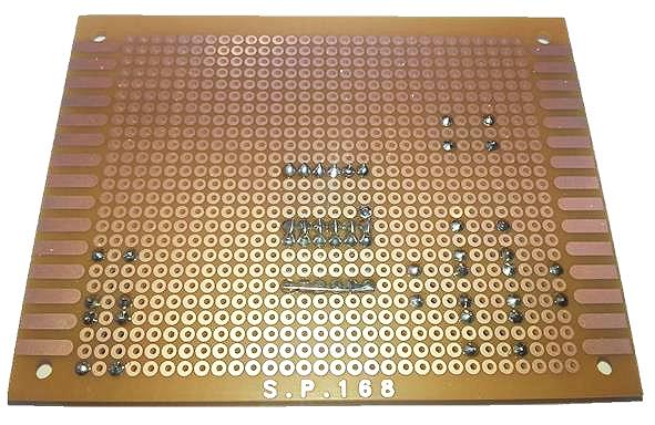
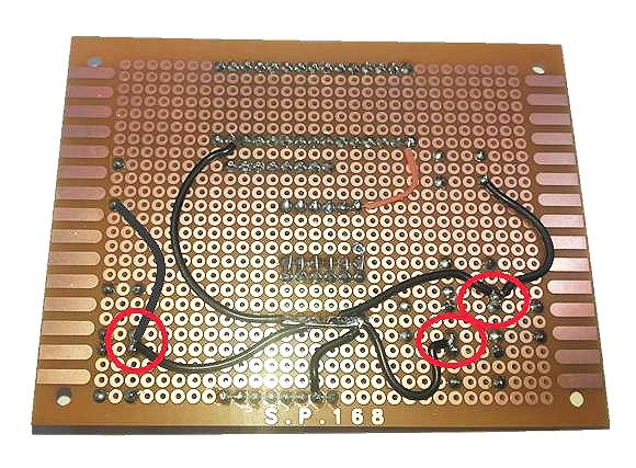
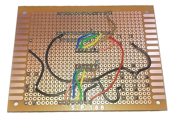
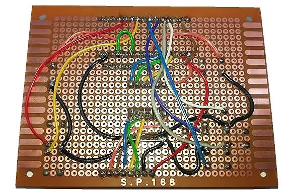
The wiring on the back is what makes it all work, so this has to be right. The LCD Screen runs off 3.3V power and logic levels, which is why we have the resistors on the board- they form a voltage divider, which turns 5V signals into 3.3V signals. In the table below, some of the connections are made directly, and some are made via the voltage divider.

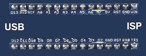
While doing this, I've found it helpful to have this diagram of the underside of a Nano, with pins marked. It's how the Nano pins are laid out on the wiring side of the board:

We'll show how we did the wiring below. Firstly, make all the ground connections. We did this by running a wire from the Nano GND to the voltage divider T column, and then making all the other connections from there.

Note that in the red circles, the black wire goes to terminals on two switches, which simplifies our wiring a bit more. The next step is to make all the LCD Screen connections- here you can see how the voltage divider works. The wires from the Nano go to the resistors on column L, and come out from the resistors on column P/Q to their designated connections on the LCD Screen. Note for the LCD Screen there are five voltage divider connections and one red wire going straight to the 3.3V supply on the Nano.

Then we can do the wiring for the buttons, speaker and battery monitor. Make sure that you use the same terminals on the Push Buttons as shown- some of the terminals are wires straight through and the Nano will think the buttons are pushed down permanently if they are wired wrong.

This completes the wiring of the Game Machine

To compile your own sketches for the Arduino Game Machine, you can use the Gamebuino libraries. This can be installed by the Library Manager in Arduino by clicking Sketch > Include Library > Manage Libraries and searching for 

gamebuino

.

If this doesn't work, the library can also be downloaded from here: 

. The library includes a few examples, but not any games.

You'll need to have this library installed for the Tic-Tac-Toe game to work, and also copy the TICTACTOEforArduinoGameMachine sketch folder from the TICTACTOEforArduinoGameMachine.zip file to your Arduino sketch folder.

After this, it should simply be a case of selecting the Nano board and correct COM port and pressing upload. You should get a chime sound as well as the above left graphic when the sketch is correctly uploaded.

If the sketch doesn't compile, check that the library is installed correctly. If you get missing picture or sound, check the wiring to that component.

Pressing the A button (bottom right) should start the game, while pressing B (above A) will change the volume. C (top left) will cause the Arduino Game Machine to restart from the main menu (more about what the SD function is later).

After pressing A, follow the instructions on the screen, and use the directional buttons to place the X when it is the Player turn. Check that all the buttons work in the correct direction, and fix the wiring if necessary.

We've found a few pre-made games at 

 For example, to upload the Asterocks game, create an 'asterocks' folder in your Arduino folder, and copy the contents of the .zip file into this folder.

Then open the asterocks.ino sketch file, and choose 'Nano with ATMega 328', and the correct serial port, and click upload. If the sketch doesn't compile, then check that you have the Gamebuino library correctly installed.

There are also more games on the github page:

There are more games available from 

 but they are only in HEX format, so can't be compiled by Arduino. The HEX format is what the sketch gets converted to before it is uploaded to the Arduino.

There is a way to upload HEX files directly by using the XLoader program. Download the zip file from 

, and copy the XLoader file to somewhere you can access it, such as 'My Documents', then run the XLoader program.

For Device, choose Uno(ATMega 328)- even though we're using an Nano, they have the same microcontroller, and this works fine. Set the Baud Rate to 57600 (this is what the Nano usually uses for upload), then select your HEX file and COM Port and press Upload. The upload should cause the lights on the Nano to flicker like a normal Arduino Upload, and then the game should start within a few seconds.

Future Improvements

You might have looked at the official 'Gamebuino', and seen that it boasts a few more features than our version.

Similar projects you may be interested in

Entertainment
Arduino Learning
Difficulty

Entertainment
Music Beat Bar
Difficulty

Metronome
Entertainment
Metronome
Difficulty

Entertainment
Memory Gesture Game
Difficulty