DC Power Meter
Difficulty
Summary
Have a power source you need to measure the voltage of? Or want to see how much current you're putting through your projects? Have a go of our easy mini DC Power Meter project. Comes with Banana post screw terminals which will make it easier to connect anything to it, from any source.
Materials Required
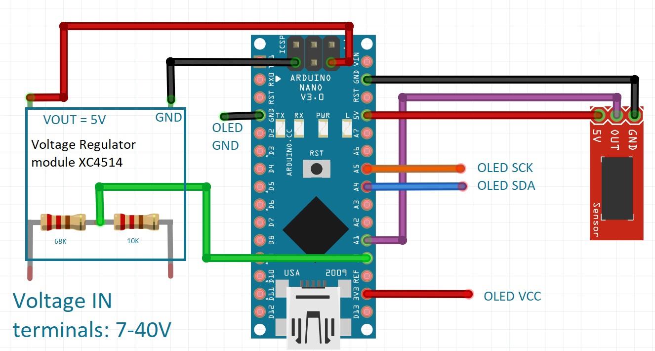
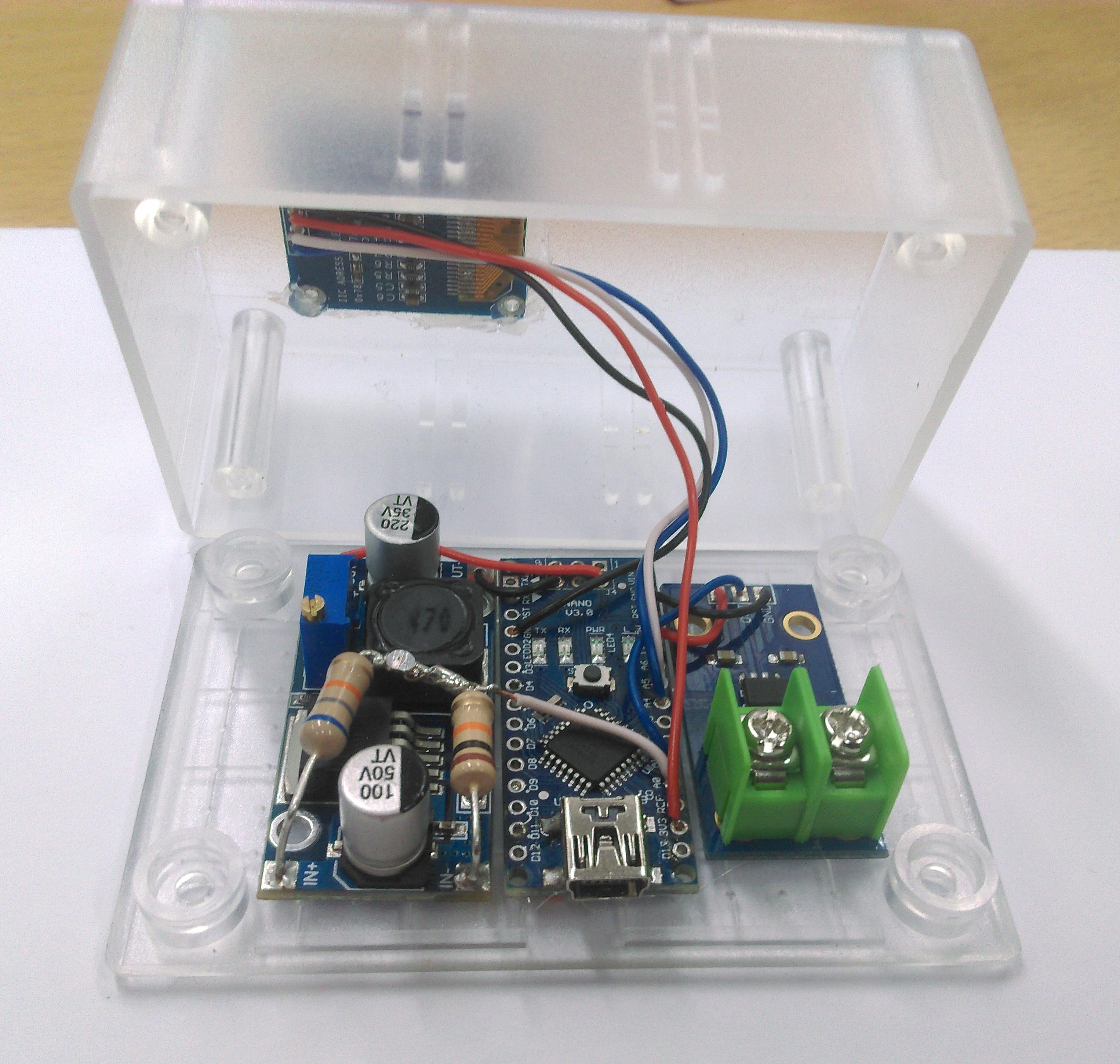
| 1 | Arduino Compatible Nano Board | XC4414 |
| 1 | Arduino Compatible 30A Current Sensor Module | XC4610 |
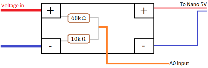
| 1 | Arduino Compatible DC Voltage Regulator Module | XC4514 |
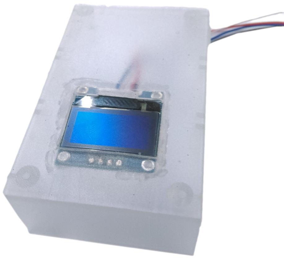
| 1 | Jiffy Box - Clear - 83 x 54 x 31mm | HB6005 |
| 1 | Arduino Compatible Monochrome OLED Display Module | XC4384 |
| 2 | Black Deluxe Binding Post | PT0454 |
| 2 | Red Deluxe Binding Post | PT0453 |
| 1 | 10k Ohm 1 Watt Carbon Film Resistors - Pack of 2 | RR2798 |
| 1 | 68k Ohm 1 Watt Carbon Film Resistors - Pack of 2 | RR2818 |
| 1 | Economy Breadboard Jumper Kit - 5 colours | WH3032 |
Resources
Table of Contents


.jpg%3Fbranch%3Dprod&w=1920&q=75)
Future Improvements
Similar projects you may be interested in