Benchtop Power Supply
Difficulty
Power
Summary
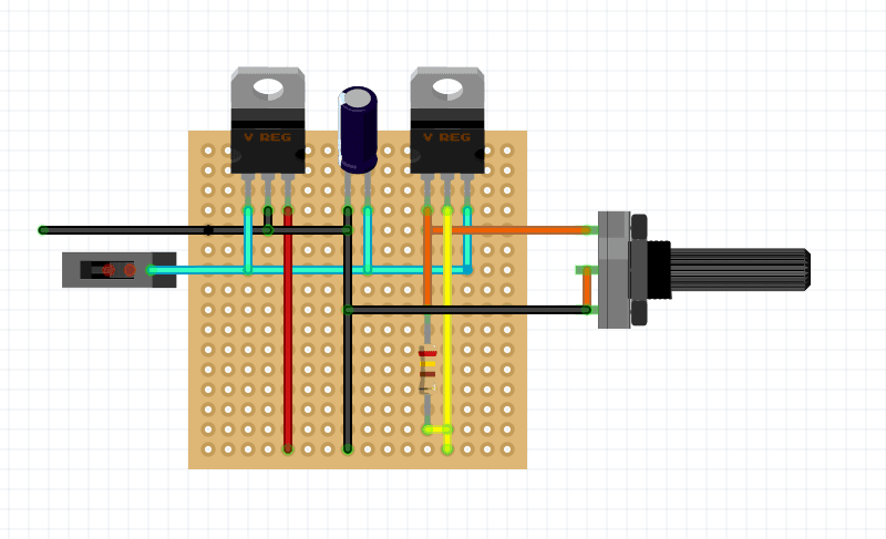
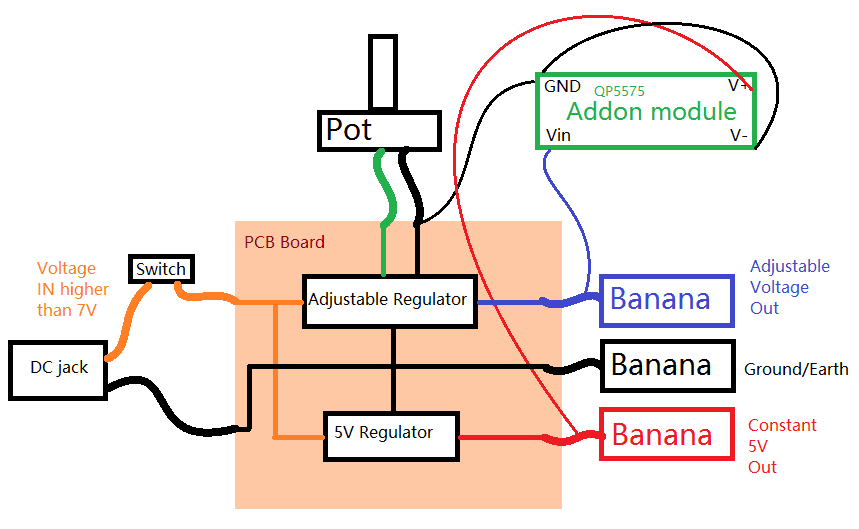
What better way to get back in to work with your own personal benchtop power supply. Uses a LM317 for power output and provides a separate 5V rail.
You will need a power supply higher than 7V to power this unit, and it will only be able to power up to 2V less than the power you give it.
Materials Required
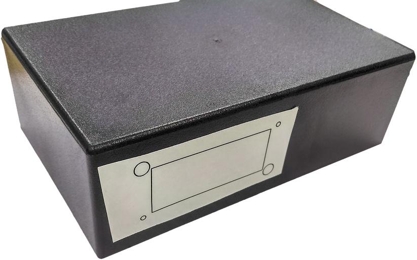
| 1 | Jiffy Box - Black - 158 x 95 x 53mm | HB6011 |
| 1 | LM317T +1.2 - 37V 1.5A Adjustable Voltage Regulator | ZV1615 |
| 1 | 7805 +5V 1A Voltage Regulator TO-220 case | ZV1505 |
| 2 | TO-220 Heatsink 15.8mm | HH8516 |
| 1 | Universal Pre-Punched Experimenters Boards - Medium | HP9552 |
| 1 | Zinc Oxide Heatsink Compound - 10g Tube | NM2010 |
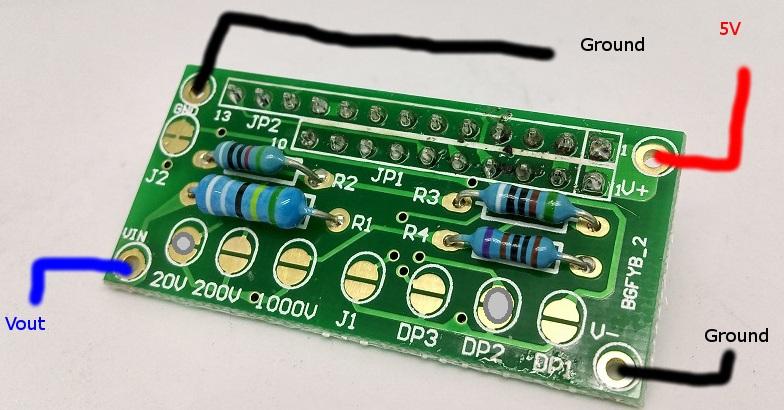
| 1 | LED 3.5 Digit Panel Meter - Low Cost | QP5580 |
| 1 | SPDT Miniature Toggle Switch - Solder Tag | ST0335 |
| 1 | Add On Board For QP-5570/80 Panel Meters | QP5575 |
| 1 | 5k Ohm Linear (B) Single Gang 16mm Potentiometer | RP7508 |
| 1 | 240 Ohm 0.5 Watt Metal Film Resistors - Pack of 8 | RR0557 |
| 1 | 10uF 25VDC Electrolytic RB Capacitor | RE6070 |
.png%3Fbranch%3Dprod&w=3840&q=75)

Similar projects you may be interested in
.jpg%3Fbranch%3Dprod&w=1080&q=75)