The construction of the tree of LED's might look a bit tricky, but if you following the steps carefully, you should have no trouble. We'll start by carefully bending the legs of the LED's. The legs don't like being bent and straightened and bent again, in case they break off.
Start by bending the legs 90 degrees so that they point straight out the sides (1), then about 3mm further along the legs, bend the legs straight down (2). We want to make sure that the legs run outside the main body of the LED. Finally, bend the left leg towards you be about 10 degrees and bend the right leg back by 10 degrees. The result should be like (3).


You'll notice that one leg is longer than the other. This is normal, and is used to differentiate the cathode (negative terminal, and it also has a flat on the body of the LED near it) from the anode (or positive terminal). We'll need to know this later so our LED's go onto the board the correct way.
The next step is to fit the resistors to the prototyping board- we'll do this because they'll sit lower than the LED's, and they'll be hard to get to if the LED's went in first.

Notice that one end of the resistors is at the fourth row of holes in line with the large hole at the end of the prototyping board, and they are spaced three holes apart in line with D1, D4, D7, between D9 and D10, and between D12 and D13. The other end of the resistor is in the sixth row of holes away from the analog pins.
Then we mount the LED's. The short leg of the LED gets mounted on the end of the resistor leg- this gives it a bit more height. Then the other leg of the LED gets soldered to a hole on the protoboard three holes over, and three holes across. For most of the LED's, this means their anode (the long leg) is actually in line with the next resistor over. This should give us the legs of the LED's running clear of either side of the bodies. Note the colours too- we've done a red LED at the end and three green LED's in the middle. Keep following the pattern from the above photo as we build up.

Solder the negative lead of the next row of LED's to the negative lead of the previous row (we do this first because it's shorter). Then solder the positive lead of the LED to the positive LED of the adjacent LED below. If you need to, you can now adjust the negative lead.

As we keep building up, note that all the negative leads are on the side with the resistors, and all of them slope to the right at roughly the same angle, and all the positive leads are on the other side, sloping the other way. Complete the rows of three, two and one LED's in a similar fashion, and check against the picture below.

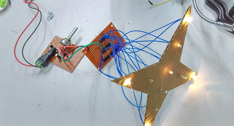
The final wiring step is to connect the LED matrix we have built back to the pins that go to the Uno board. In order, the positive leads go to D2, D3, D4, D5 and D6, while the resistors go to A1, A2, A3, A4 and A5.

All that's left is to plug the shield into the Uno, and the hardware is complete.

All that's left is to plug the shield into the Uno, and the hardware is complete.
.jpg%3Fbranch%3Dprod&w=1200&q=75)

.jpg%3Fbranch%3Dprod&w=1080&q=75)