Progress Bar

Skip to main content

Jaycar
...

Intruder Alert

Intruder Alert

Difficulty
Security & Surveillance

Summary

The ideas don't just stop at a PIR sensor either; The code is very simple to understand and through the IFTTT service you can cause anything to trigger; such as using a button or light sensor.

Materials Required

1Wi-Fi Mini ESP8266 Main BoardXC3802
1Arduino Compatible Wi-Fi Mini Prototyping ShieldXC3850
1Duinotech Arduino Compatible PIR Motion Detector ModuleXC4444
1Red 5x2mm LED 5mcd Rectangular DiffusedZD0230
1Green 5x2mm LED 15mcd Rectangular DiffusedZD0232
11.4mm SPST Micro Tactile SwitchSP0601

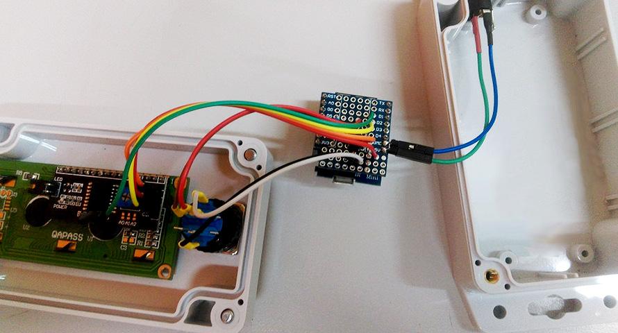
The connections are fairly simple on this board; as the LEDs are powered straight from the GPIO pin (being 3v, it's low enough not to cook the LED), as well as the button to ground, and the signal from the PIR sensor.

ESP8266 Pin

Connects through

Towards

D0

Green LED

Ground

D6

Red LED

Ground

D8 (pulled-down)

Button

3v3

D7

PIR (middle pin)

-

Use a spare extension header ( female header with long legs) to connect the PIR sensor to the board, by splitting off a section of 3 from it. You can use a sharp knife to trim away the edge and make it more neat in appearance.

The view of the top side of the board is shown below. It is 

important

 to get the orientation correct, so make sure the pin in the top left is TX when looking at the top, and the bottom-rightmost pin is 3v3.

The bottom-side of the board is reversed when you flip it over. A good idea might be to place the components in and bend the leads so that they stay in place while you turn it over to solder.

Be sure to get the LED's in the correct orientation as well. The longer lead on the LED is the positive, which goes into the D0/D6 holes. The negative side (has a flat edge on the globe of the LED) faces towards the middle of the PCB board.

It will be easier to do the solder of the components before you put on the two headers. Because we might want to use the ESP8266 in later breadboard designs, we are putting the male connectors on the ESP8266 (facing downwards) and the female connectors on our prototyping shield.

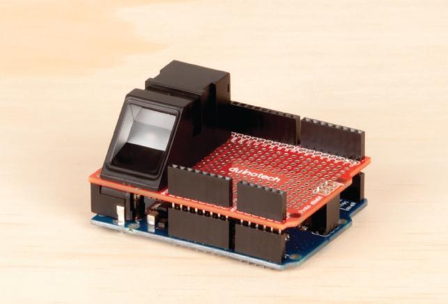
It bears repeating that the pins must match up, so check that the orientation is correct, you can then put the two halves together, and put the PIR sensor on the shield as shown below.

This has the metal part of the 

 facing downwards, and the PIR on top.

There's 3 bits of information you need to place in the intruder.ino source code:

WiFi SSID

WiFi Password

IFTTT URL

You can put in the WiFi SSID (the name of the network) and the password as normal; then for the IFTTT url, head to 

 and create an account or log in.

Firstly, we have to connect 2 services to our account, then bind them together. the IFTTT page seems to change often so screenshots won't help, however the idea is the same:

Once you have logged into your account:

Explore or Search for "Webhooks" service, and connect your account to that.

Explore or Search for "Notifications" service, and connect your account to that as well.

Then in the top right, click your avatar to bring the drop-down menu, and press "create". You should come to a large screen that says "If +This Then That"

Click on the +This, search for webhook.

"Receive a Web Request"

Event name: "motion"

Create Trigger

Now you should be back at large writing;

Click on the +That, search for notifications

"Send a notification from the IFTTT app"

Put your own custom message if you want to.

Create Action

Now you should be on the review screen which will show you what the total process will look like. Click Finish once you are satisfied.

You will need the webhook key in order to activate it. Head to the webhook settings here: 

 and find the URL.

You can notice the last portion of your maker URL, after the /use/ will be the key. For instance, if your maker URL is:

1 https://maker.ifttt.com/use/bhPYcN-gOSLrYLGWg4r8Lf

Then your maker key is bhPYcN-gOSLrYLGWg4r8Lf.

Edit the source code and change the EVENT_NAME to be the event name you set while setting up the connection, which was "motion" in our example. Then change the MAKER_KEY to be your Maker Key above.

Finally, your ifttt_url should look something like this, replacing motion with your event name, and containing your key.

1 const char *ifttt_url = "https://maker.ifttt.com/trigger/motion/with/key/Rg3Pj8f_-qyJTcT1YhhVb";
2

Use the IFTTT app to get notifications on your phone. When the ESP8266 is first powered up, you should see the red light blinking at a moderate pace. This is in a 

disarmed

 state.

When it detects motion, the green light will flash twice. You can use this to test when motion is detected.

When it is ready, you can hold the button down for 1-2 seconds. All lights should go off, with the red then flashing 3 times, before staying on for 3 seconds.

This signifies that the ESP8266 has been armed. if everything has been set up correctly it will now alert your phone when it detects motion.

This project is fairly simple to understand, as it simply checks the PIR sensor to see if it has detected movement and then fetches a website.

This could be connected from and to anything. The great power of IFTTT makes it versatile while still being simple to understand and use. You can also send data to the ifttt service using arduinoJSON and POST requests, which we have done in one of our data-logger projects.

One issue with the project is that it won't always pick up motion due to how the LED's are blinking. This is on purpose as it makes the code easier to understand, but if you wanted to do it properly, you would get rid of all the delays and use millis() instead. - this can complicate the code quite a bit but we can explore this in github branch for the project. You're welcome to submit your attempts and we can help out.

If you are having issues with it always detecting motion, or not detecting motion, try a simple sketch (such as:)

1 void loop(){ digitalWrite(led_green, digitalRead(pir_sense)); delay(100);}

Adjust the potentiometers so that you can get the sensitivity right for where you want to use it, This could take some trial and error to find the sweet spot.

The PIR sensor will not do good looking at sunlight, as sunlight contains IR, which will move throughout the day (as the shadows / sunlight is moving across the ground).

If you have issues sending notifications, open up the Serial Monitor and see what the information says. It should say "congratulations" -- if it does, make sure your ifttt connection is set to the same event name, and that you have the IFTTT app installed on your phone.

Explore IFTTT Services: 

Similar projects you may be interested in

IOT Button Notifier
Security & Surveillance
IoT Button Notifier
Difficulty

Security & Surveillance
GPS-Tracker
Difficulty

Fingerprint Login
Security & Surveillance
Fingerprint Login
Difficulty

Pan Tilt Camera
Security & Surveillance
Pan Tilt Camera
Difficulty